
Liquid crystal display device

Inactive Publication Date: 2012-06-28
SHARP KK
View PDF4 Cites 17 Cited by
  • Summary
  • Abstract
  • Description
  • Claims
  • Application Information

AI Technical Summary

Benefits of technology

[0029]According to the present invention, the contents of the backlight scanning is changed properly depending on which of the first multi-speed drive mode and the second multi-speed drive mode is executed. As a result, smooth moving image display can be realized as the creation of motion blur or multi-contour in displaying moving images is suppressed in the first multi-speed mode, and the creation of multi-contour in displaying moving images can be suppressed as much as possible also in the second multi-speed mode.

Problems solved by technology

The liquid crystal display device poses a problem of motion blur occurring in displaying moving images when operated by a hold-type drive method of constantly turning on the backlight source.
This technology shortens a display time of 1 frame, thus reduces image persistence feelings.

Method used


Image

  • Liquid crystal display device
  • Liquid crystal display device
  • Liquid crystal display device

Examples


working example 1

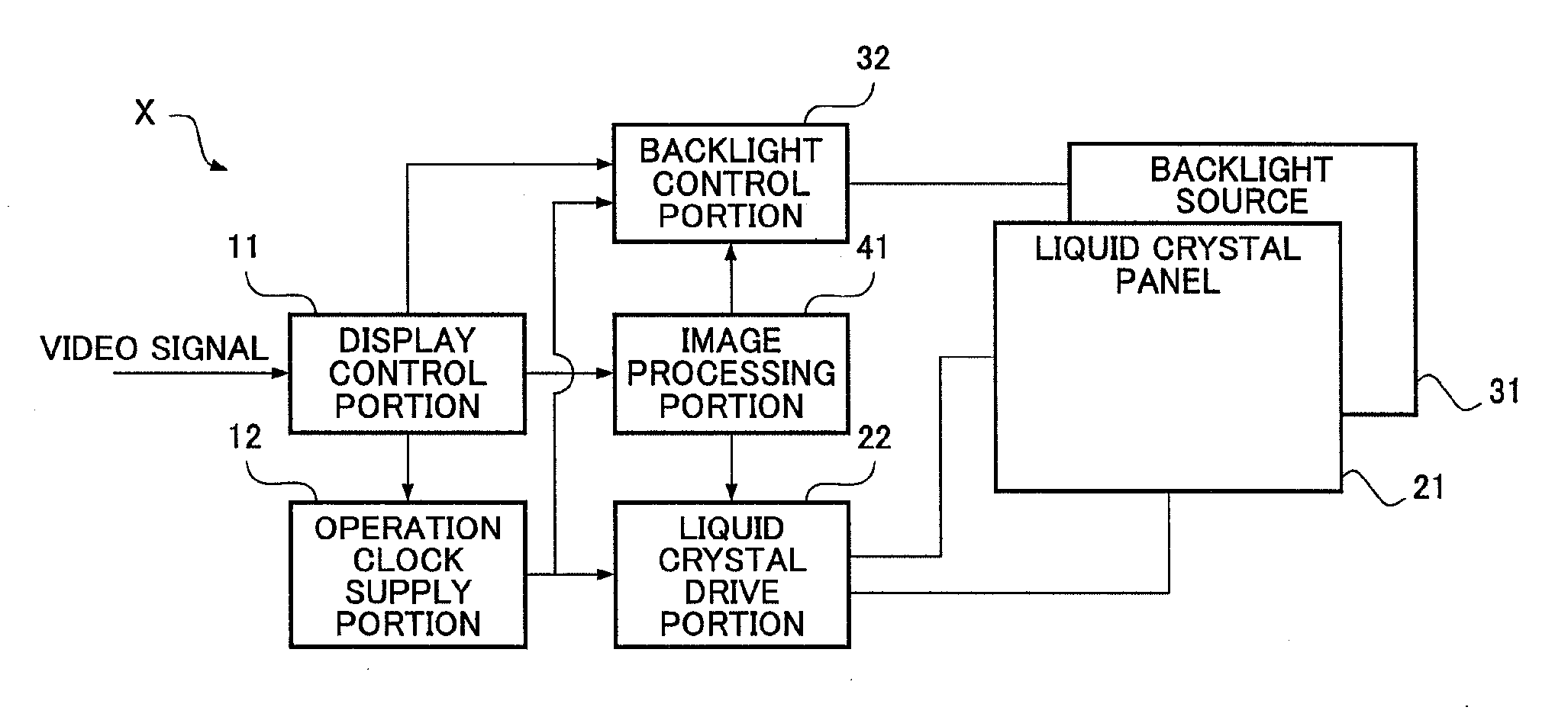
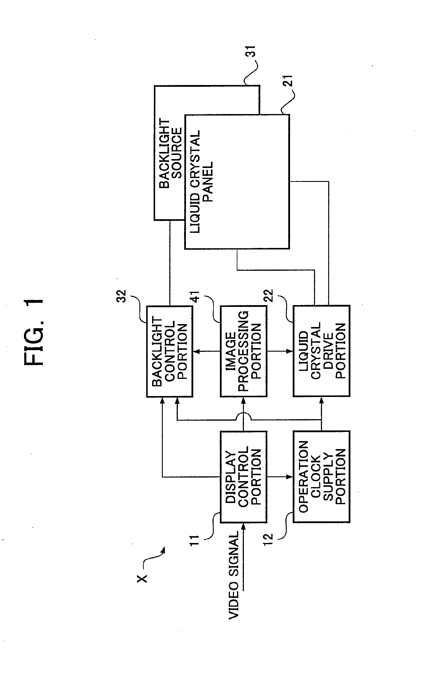
[0091]Other configuration examples of the liquid crystal display device X will hereinafter be described with reference to diagrammatical views of FIGS. 5 and 6.

[0092]The above embodiment is described as an example in which when the overlapped image output mode is executed, the execution cycle of the intermittent turning-on action in the backlight scanning is changed into a cycle longer than (twice) the cycle of vertical synchronization signal.

[0093]It is conceived in another working example that the backlight scanning may be invalidated in the overlapped image output mode.

[0094]Specifically, when the overlapped image output mode is executed, the backlight control portion 32 may suspend the backlight scanning and execute a hold-type drive process of constantly turning on the backlight source 31, as depicted in FIG. 5. As a result, as indicated in FIG. 7(a), multi-contour are prevented, which multi-contour are created when the intermittent turning-on action in the backlight scanning i...

working example 2

[0099]The above embodiment is described as an example in which upon detecting a failure in normally generating the interpolation image when the interpolation image insertion mode is executed, the image processing portion 41 suspends the interpolation image insertion mode and executes the overlapped image output mode. When the interpolation image is generated normally, the execution cycle (turning-on period+turning-off period) of the intermittent turning-on action in the backlight scanning matches the cycle of writing 1 frame onto the liquid crystal panel 21 by the liquid crystal drive portion 22, that is, the cycle of the vertical synchronization signal.

[0100]In a working example 2, a modification of the process carried out in the interpolation image insertion mode is described.

[0101]Specifically, when the interpolation image insertion mode is executed by the liquid crystal drive portion 22 and the image processing portion 41, if the precision of an interpolation image signal genera...


PUM


Abstract

To provide a liquid crystal display device capable of reducing the occurrence of a multi-contour in the display of a moving image to the minimum, the cycle of execution of an intermittent lighting operation in backlight scanning and the cycle of a vertical synchronization signal are made equal when an interpolation image insertion mode in which an interpolation image signal generated on the basis of two or more continuous frame images is inserted between frames and written into a liquid crystal panel is executed, and the cycle of the execution of the intermittent lighting operation in the backlight scanning is made longer than the cycle of the vertical synchronization signal (or the backlight scanning is disabled) when an overlapped image output mode in which the same frame image is written into the liquid crystal panel continuously n times is executed.

Description

TECHNICAL FIELD[0001]The present invention relates to a liquid crystal display device having a liquid crystal panel and a backlight source, and, more particularly, to a technique for preventing motion blur in displaying moving images by intermittently turning on backlight source.BACKGROUND ART[0002]Recently, a liquid crystal display device having a liquid crystal panel and a backlight source has come into wide use as a TV set, display device, etc. The liquid crystal display device poses a problem of motion blur occurring in displaying moving images when operated by a hold-type drive method of constantly turning on the backlight source.[0003]FIG. 7(a) depicts a visually recognized image F2 that is recognized by a viewer when an original image F1 moves on a liquid crystal display panel driven by a hold-type drive method of constantly turning on a backlight source. As depicted in FIG. 7(a), in a state of hold-type drive, motion blur due to an afterimage persisting on the human retina i...

Claims


Application Information

Patent Timeline
IPC IPC(8): G09G5/10G09G3/36
CPCG02F1/133602G02F2001/133601G09G3/342G09G2310/0237G02F1/133603G09G2310/08G09G2320/0261G09G2340/0435H04N7/0132G09G2310/024G02F1/133601
Inventor ONIKI, MOTOYUKI
Owner SHARP KK
Learn More