
Digital clock modulator

a clock modulator and digital clock technology, applied in the direction of generating/distributing signals, pulse techniques, instruments, etc., can solve the problems of inability to use systems, modulating clock generating sources, and arbitrary modulation not generating optimal emi reduction, etc., to reduce emr and increase clock modulation depth

Inactive Publication Date: 2008-10-14
STMICROELECTRONICS PVT LTD
View PDF12 Cites 1 Cited by
  • Summary
  • Abstract
  • Description
  • Claims
  • Application Information

AI Technical Summary

Benefits of technology

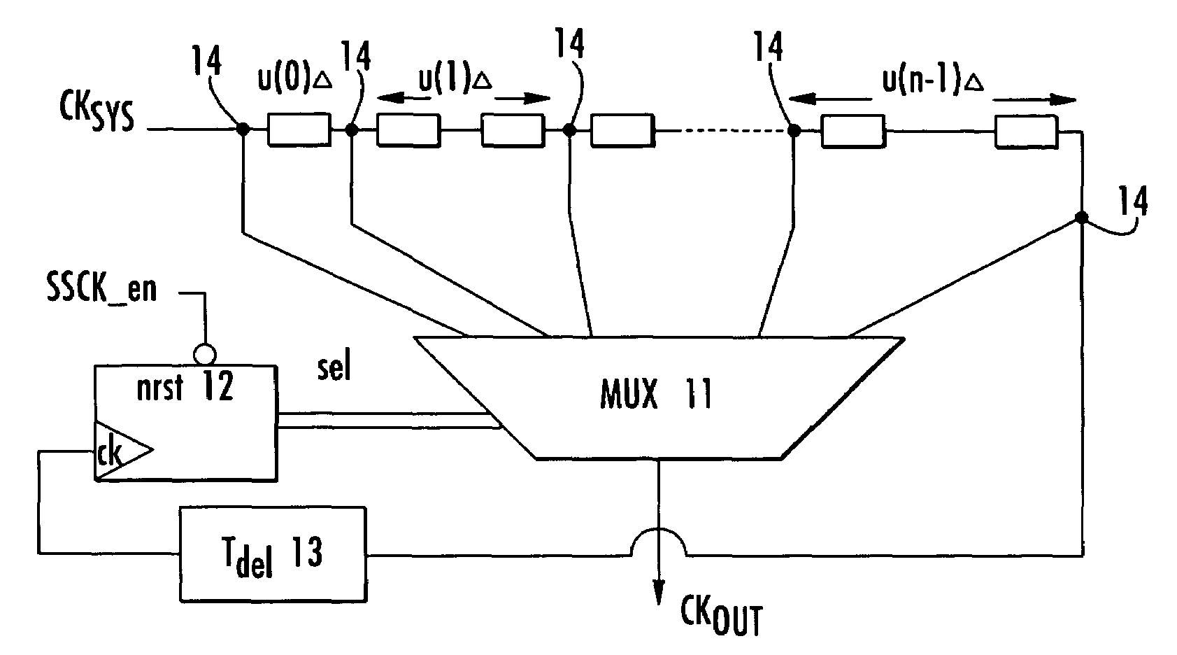
"The invention provides an improved digital clock circuit that can reduce emitted electro-magnetic radiation (EMR) and smoothly modulate the clock period. The circuit includes a plurality of delay elements connected in series, a multiplexer, and a control block. The delay elements receive an unmodulated clock signal and the multiplexer selects among the outputs of the delay elements. The control block generates complementary control signals for enabling the multiplexer to operate in a desired sequence. The invention also includes a delay interpolator for providing a finer resolution of the clock modulation. The method for reducing EMR from digital circuits involves connecting a plurality of delay elements in series, multiplexing selected outputs, and delaying the clock to the last element of the delay chain. The invention provides a flexible design capable of producing any desired clock-period modulating pattern."

Problems solved by technology

Frequency modulation is a predominantly analog technique and has overheads in terms of implementations in the integrated circuit (IC).
Moreover, any arbitrary modulation does not generate an optimum EMI reduction.
In other words, randomly modulating a clock generating source may not provide improved attenuation of EMI.
However, these techniques cannot be used for systems in which the PLL is a procured object, that is, one which cannot be modified.
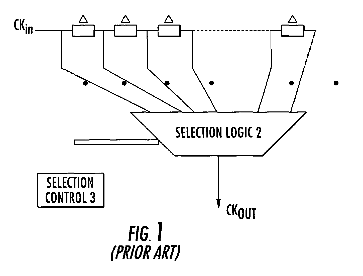
This technique does not provide optimum spread spectrum EMR reduction since the energy concentrates around two frequencies: 1 / (Tck+Δ) and 1 / (Tck−Δ) only.
This technique is not suitable for most integrated digital systems since it calls for varying the supply voltage.
However, the pseudo-random nature results in a sharp odd time period variation while other time periods are very slow.

Method used


Image

  • Digital clock modulator
  • Digital clock modulator
  • Digital clock modulator

Examples


Embodiment Construction

[0042]The circuit of the present invention is based upon manifestation of the following mathematical analysis. Time Period modulation and its spectral representation will initially be discussed.

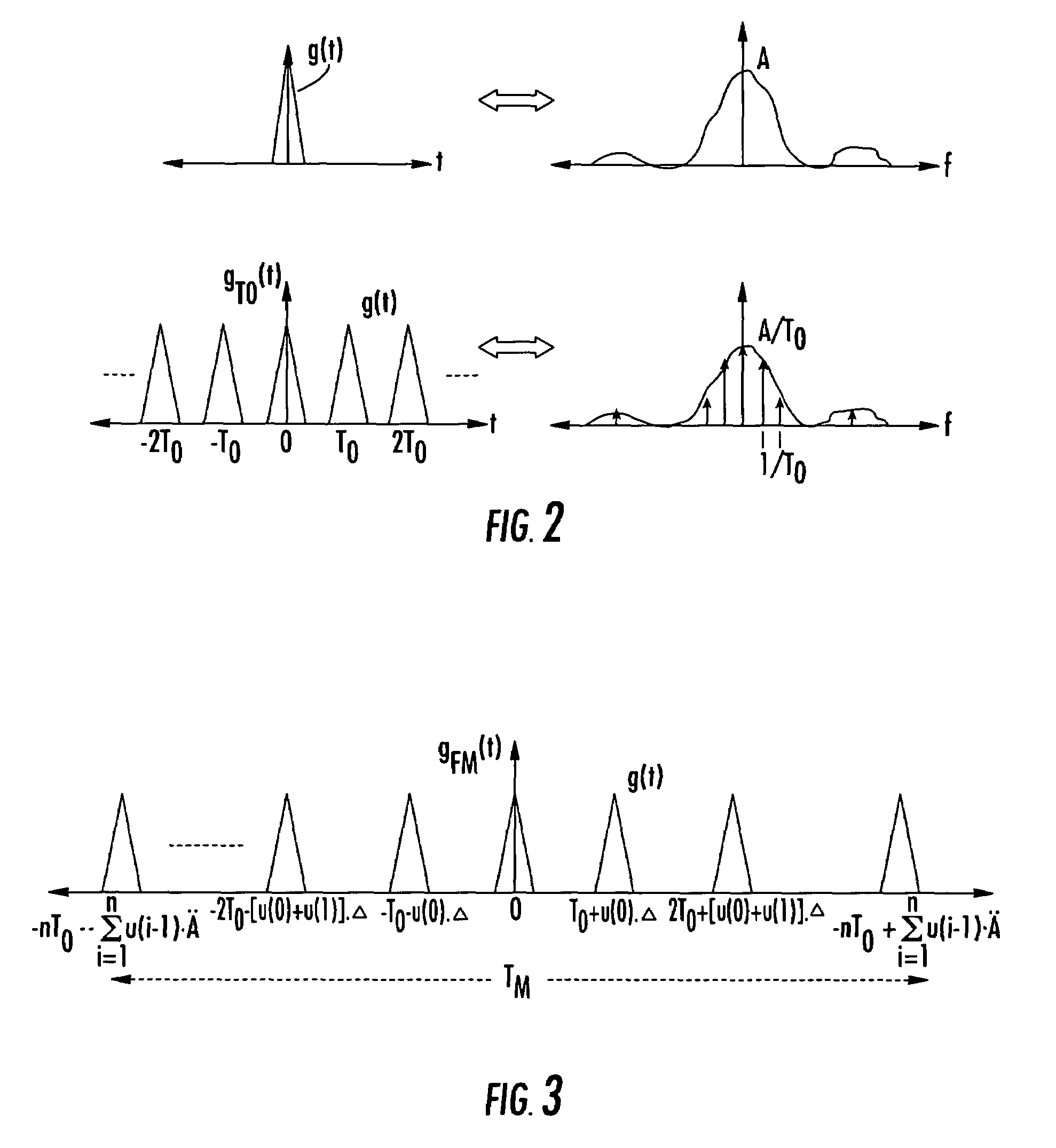
[0043]An arbitrary time dependent signal g(t) occurring in the time period T0 can be represented in the frequency domain by its Fourier transform G(f). It can be switching current spikes, for example. FIG. 2 shows such an arbitrary time dependent signal g(t) and its frequency domain representation G(f). The Fourier Transform is given by equation (1):

g(t)G(f)   (1)

[0044]If g(t) repeats every T0, as shown in FIG. 2, then gT0(t) in the frequency domain would be represented by equation (2):

[0045]gT0⁡(t)⇔1T0·∑m=-∞+∞⁢G⁡(mT0)·δ⁡(f-mT0)(2)

where, the Dirac deltas

[0046]δ⁡(f-mT0)

are the discrete frequency components in the frequency domain occurring at harmonics of frequency (1 / T0). The amplitude is scaled by 1 / T0 over the same Fourier transform function G(f) of equation (1).

[0047]Consider a time depend...


PUM


Abstract

A digital clock modulator provides a smoothly modulated clock period to reduce emitted electro-magnetic radiation (EMR). The digital clock modulator includes a plurality of delay elements connected in series and receiving as an input an unmodulated clock signal. A multiplexer receives inputs from unequally spaced taps between the delay elements. A control block provides selection inputs to the multiplexer, and receives the unmodulated clock signal from the delay elements. The delay elements include a last delay element providing the unmodulated clock signal to the control block. The last delay element has a predetermined delay for ensuring that the delay elements and related signal paths are in a same stable state before control to the multiplexer changes.

Description

FIELD OF THE INVENTION[0001]The invention relates to an improved digital clock modulator providing a smoothly modulated clock period for reducing amplitude of electro-magnetic radiations (EMR) emitted during clock transitions.BACKGROUND OF THE INVENTION[0002]Electro-magnetic radiations (EMR) emitted by higher harmonics of a basic clock frequency of a digital circuit due to the activities at the clock edges significantly effect the normal operation of neighboring, circuits. To prevent the adverse effects of such EMR the amplitude of the emitted radiations should be kept to a minimum. Various methods have been adopted for reducing the amplitude of interfering radiations. For example, the phase / frequency of the basic clock frequency is modulated for spreading the emitted radiation frequency band for distributing the radiating energy into adjacent side-bands about each harmonic frequency. Consequently, this reduces the amplitude of higher harmonic frequencies.[0003]Frequency modulation ...

Claims


Application Information

Patent Timeline
Patent Type & Authority Patents(United States)
IPC IPC(8): G06F1/04H03K5/1252H03K5/13H03K7/04H03K7/06H04B15/04H04L7/00H04L25/00
CPCH03K5/1252H03K5/133H04B15/04H04B2215/064H04B2215/067
Inventor NANDY, TAPAS
Owner STMICROELECTRONICS PVT LTD
Learn More