
Equalization for DMT and OFDM communication systems

a communication system and equalization technology, applied in the field of equalization for receivers, can solve the problems of channel capacity being highly degraded, available channel capacity in such a system is not a smooth function of synchronization, etc., and achieve smooth signal-to-noise ratio (snr) distribution function, improve overall performance, and improve the effect of hardware implementation

Active Publication Date: 2008-10-07
NVIDIA CORP
View PDF4 Cites 4 Cited by
  • Summary
  • Abstract
  • Description
  • Claims
  • Application Information

AI Technical Summary

Benefits of technology

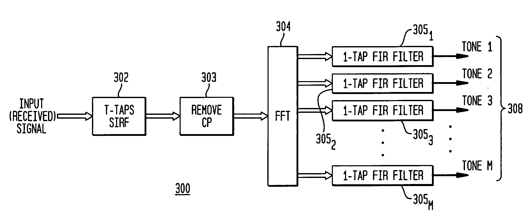
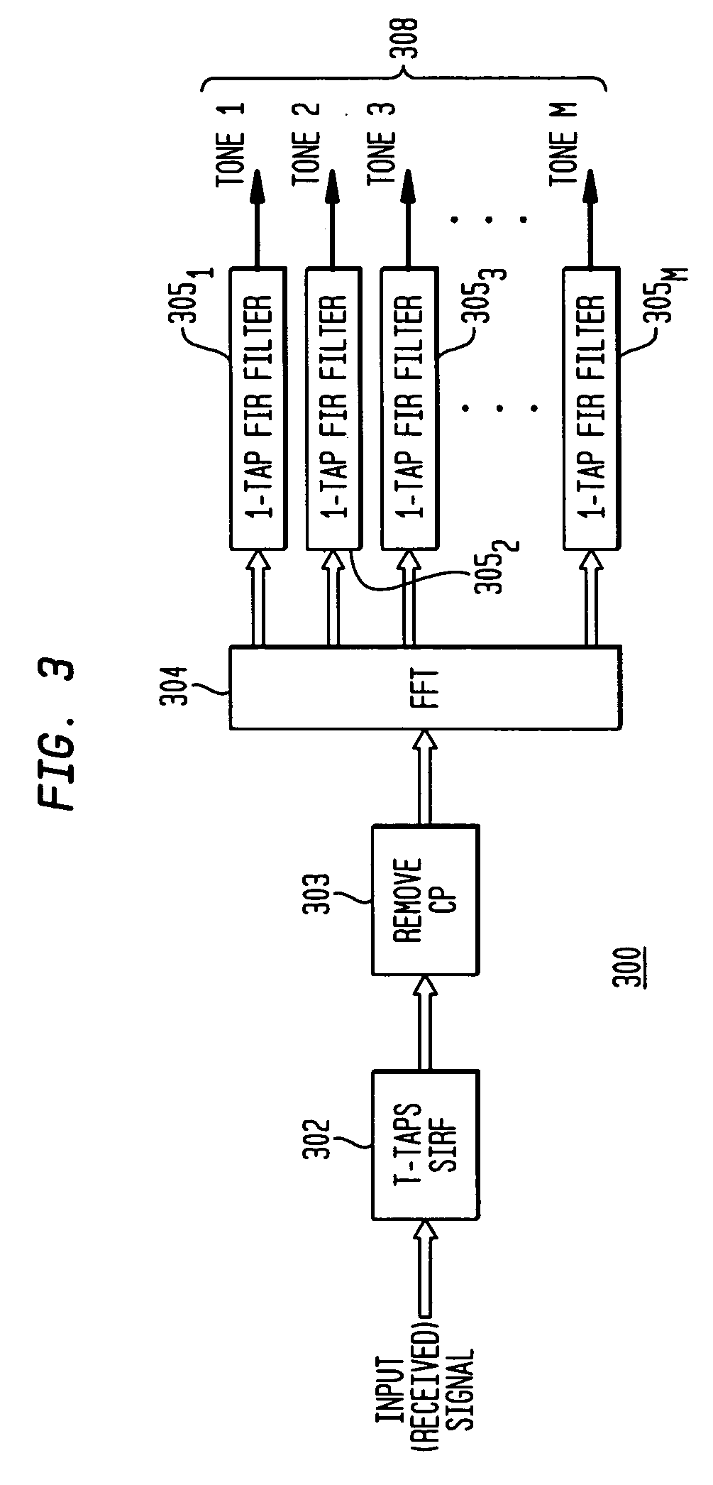
The present invention provides an equalization system for digital communication receivers that addresses the needs of per-tone systems while also providing better overall performance. The system deals with each tone individually and globally, requiring fewer variables to be determined and limiting the dynamic range of the variables. The system also retains the advantages of per-tone equalization by providing a smoother signal-to-noise ratio (SNR) distribution function versus synchronization delay. The equalization method involves time domain equalization, converting the time domain signal to a frequency domain signal, separating the signal into frequency subbands, and performing frequency domain equalization for each frequency subband using a different set of coefficients. The system can be implemented in processor-based receivers, adaptive computing-based receivers, software, and other machine-readable media.

Problems solved by technology

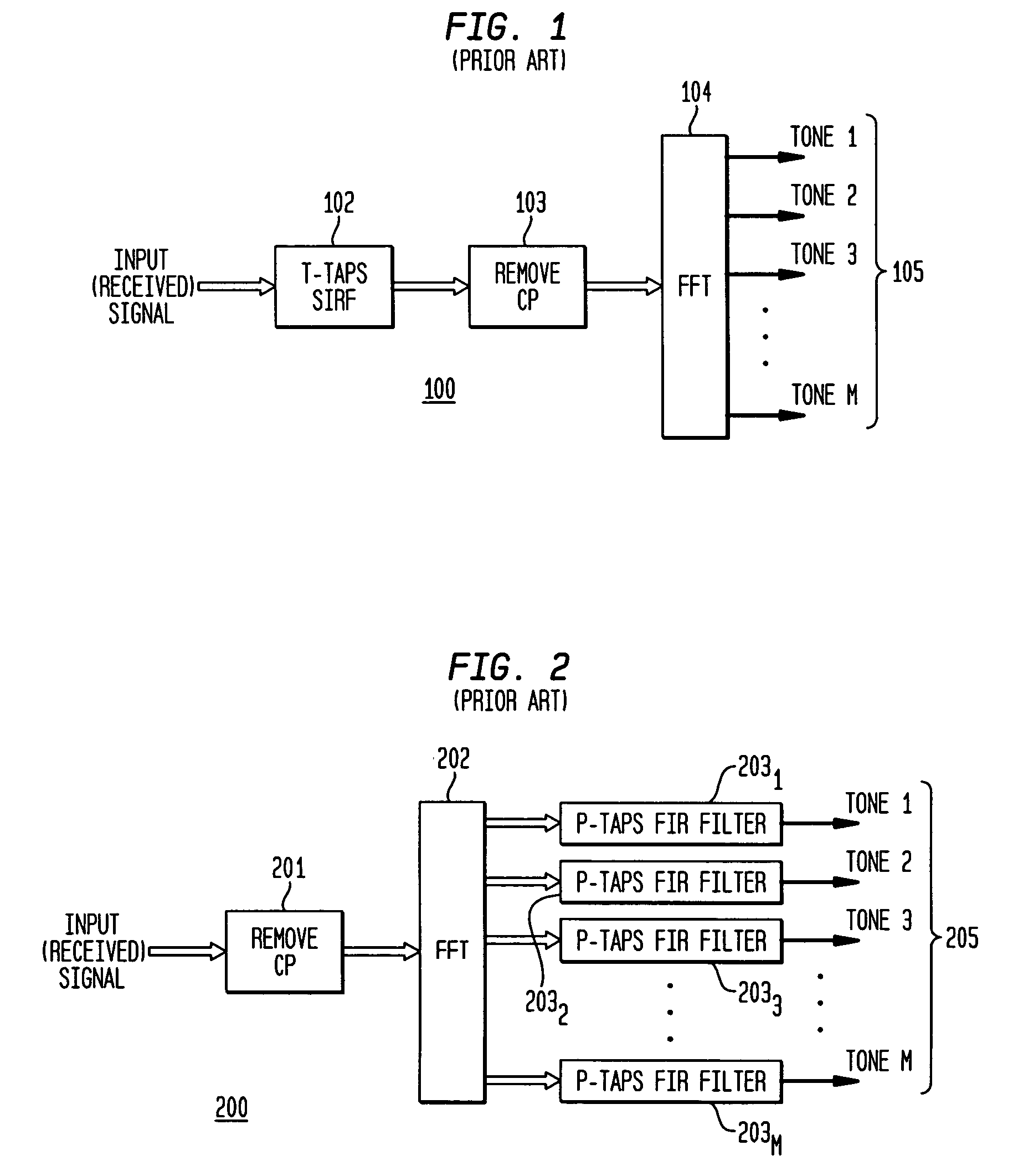
A problem arises in current implementations, however, wherein a number of time-domain equalization techniques are used to derive the coefficients of a short impulse response filter (“SIRF”) that is used to provide the time domain equalization (“TEQ”).
One disadvantage is that available channel capacity in such a system is not a smooth function of synchronization delay.
In fact, for some particular synchronization delays, channel capacity can be highly degraded.

Method used


Image

  • Equalization for DMT and OFDM communication systems
  • Equalization for DMT and OFDM communication systems
  • Equalization for DMT and OFDM communication systems

Examples


Embodiment Construction

[0019]While the present invention is susceptible of embodiment in many different forms, there are shown in the drawings and will be described herein in detail specific embodiments thereof, with the understanding that the present disclosure is to be considered as an exemplification of the principles of the invention and is not intended to limit the invention to the specific embodiments illustrated.

[0020]There is described herein an equalization for DMT-based communication systems that offers distinct advantages when compared to the prior art. A system 100 known in the prior art is illustrated in block diagram form in FIG. 1. In the system of FIG. 1, an input signal 101 is received from the physical channel (telephone lines or wireless channels, for example). As a general principal, the input signal 101 would be received through an analog front end, processed through an analog to digital converter (ADC), and subjected to appropriate digital signal processing, although these elements a...


PUM


Abstract

The invention provides a DMT or OFDM equalization system that deals with each tone not only separately, but also globally, which provides better overall performance. In the inventive system, only M+T variables are required to be determined, where M is the number of tones and T represents the number of SIRF taps. The invention defines a matrix R, in which optimal coefficients are found as the eigenvector corresponding to the smallest eigenvalue of the matrix R. The dynamic range of all variables is limited in a system in accordance with the present invention, which provides ease of hardware implementation. Furthermore, the inventive system retains the advantages of per-tone equalization by providing a smoother signal-to-noise ratio (SNR) distribution function versus synchronization delay. In addition, no effort is wasted on the equalization of unused tones, because it is unnecessary to determine the coefficients for unused tones.

Description

FIELD OF THE INVENTION[0001]This invention relates generally to equalization for receivers used in discrete multi-tone (DMT) and orthogonal frequency-division multiplexing (OFDM) communication systems and, in particular, to a combination of time-domain and frequency-domain equalization, and is more particularly directed toward a system that provides proper equalization filter coefficients for both time-domain and frequency domain equalization through application of global optimization criteria.BACKGROUND OF THE INVENTION[0002]Digital modulation schemes are increasingly employed to provide high data throughput over inherently band-limited channels. A prominent example of this is the DSL (digital subscriber line) service provided over telephone lines. Another prominent example is wireless internet communication, such as under the Institute for Electrical and Electronics Engineers (IEEE) 802.11 standards.[0003]Since telephone lines are known to provide a narrow-band channel, digital mo...

Claims


Application Information

Patent Timeline
Patent Type & Authority Patents(United States)
IPC IPC(8): H03K5/159
CPCH04L25/03012H04L25/03159H04L2025/03414H04L2025/03445H04L2025/03522
Inventor LUO, FA-LONGCHOU, DAVID
Owner NVIDIA CORP
Learn More