Fault tolerant homopolar magnetic bearings

a technology of homopolar magnetic bearings and bearings, applied in the field of magnetic bearings, can solve problems such as unstable flux couplings, faults, and the inability to retain the rotor in its spaced relation from the stator, and achieve the effect of reducing requirements and improving reliability

Active Publication Date: 2008-09-30
TEXAS A&M UNIVERSITY
View PDF4 Cites 16 Cited by
  • Summary
  • Abstract
  • Description
  • Claims
  • Application Information

AI Technical Summary

Benefits of technology

[0011]In other aspects, the invention provides an improved magnetic bearing, system, and method that improves reliability via fault tolerant operation. Flux coupling between poles of a homopolar magnetic bearing is shown to deliver desired forces even after termination of coil currents to a subset of “failed poles”. Linear, coordinate decoupled force-voltage relations are also maintained before and after failure by bias linearization. Current distribution matrices (CDM), which adjust the currents and fluxes following a pole set failure, are determined for many faulted pole combinations. The CDM's and the system responses are obtained utilizing 1D magnetic circuit models with fringe and leakage factors derived from detailed, 3D, finite element field models. Reliability results are presented vs. detection / correction delay time and individual power amplifier reliability for 4, 6, and 7 pole configurations. Reliability is shown for two “success” criteria, i.e. (a) no catcher bearing contact following pole failures and (b) re-levitation off of the catcher bearings following pole failures. An advantage of the method presented over other redundant operation approaches is a significantly reduced requirement for backup hardware such as additional actuators or power amplifiers.

Problems solved by technology

Even with multiple coil stators, however, faults are a problem, and it would be desirable to have a bearing that is fault-tolerant.
If one or more of the coils were to fail, the flux coupling that retains the rotor in its spaced relation from the stator may become unstable, allowing contact between the rotor and stator or by a “catcher bearing.”

Method used


Image

  • Fault tolerant homopolar magnetic bearings
  • Fault tolerant homopolar magnetic bearings
  • Fault tolerant homopolar magnetic bearings

Examples


examples

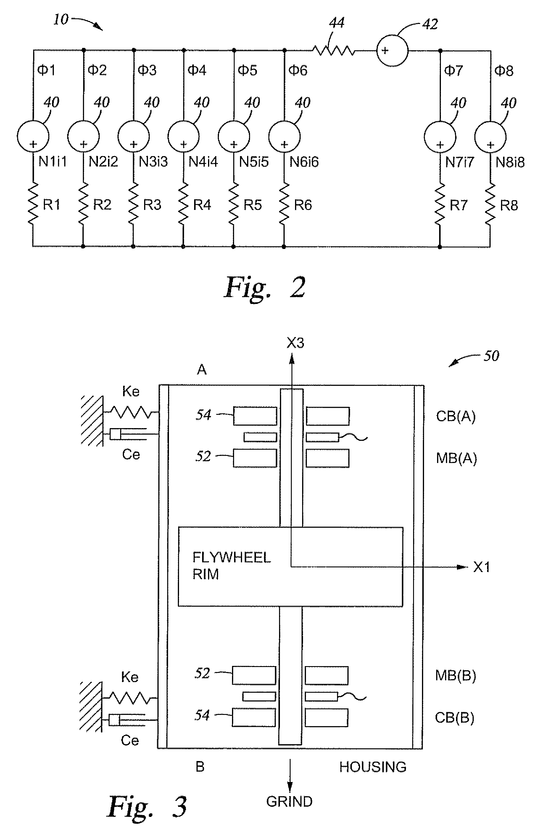
[0064]An example flywheel module illustrates operation and reliability of the redundant magnetic suspension. Table 1 lists the geometrical, inertia and stiffness parameters for the model. A suitable catcher bearing contact model can have a stiffness of 108 (N / m), a damping of 5,000 (N-s / m) and a dynamic friction coefficient of 0.1. Table 2 shows the magnetic bearing parameters for the MS model.

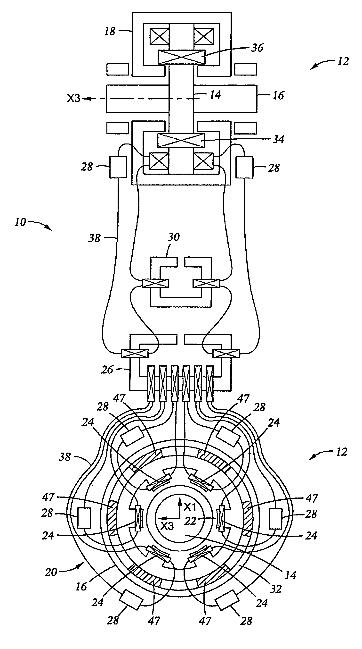
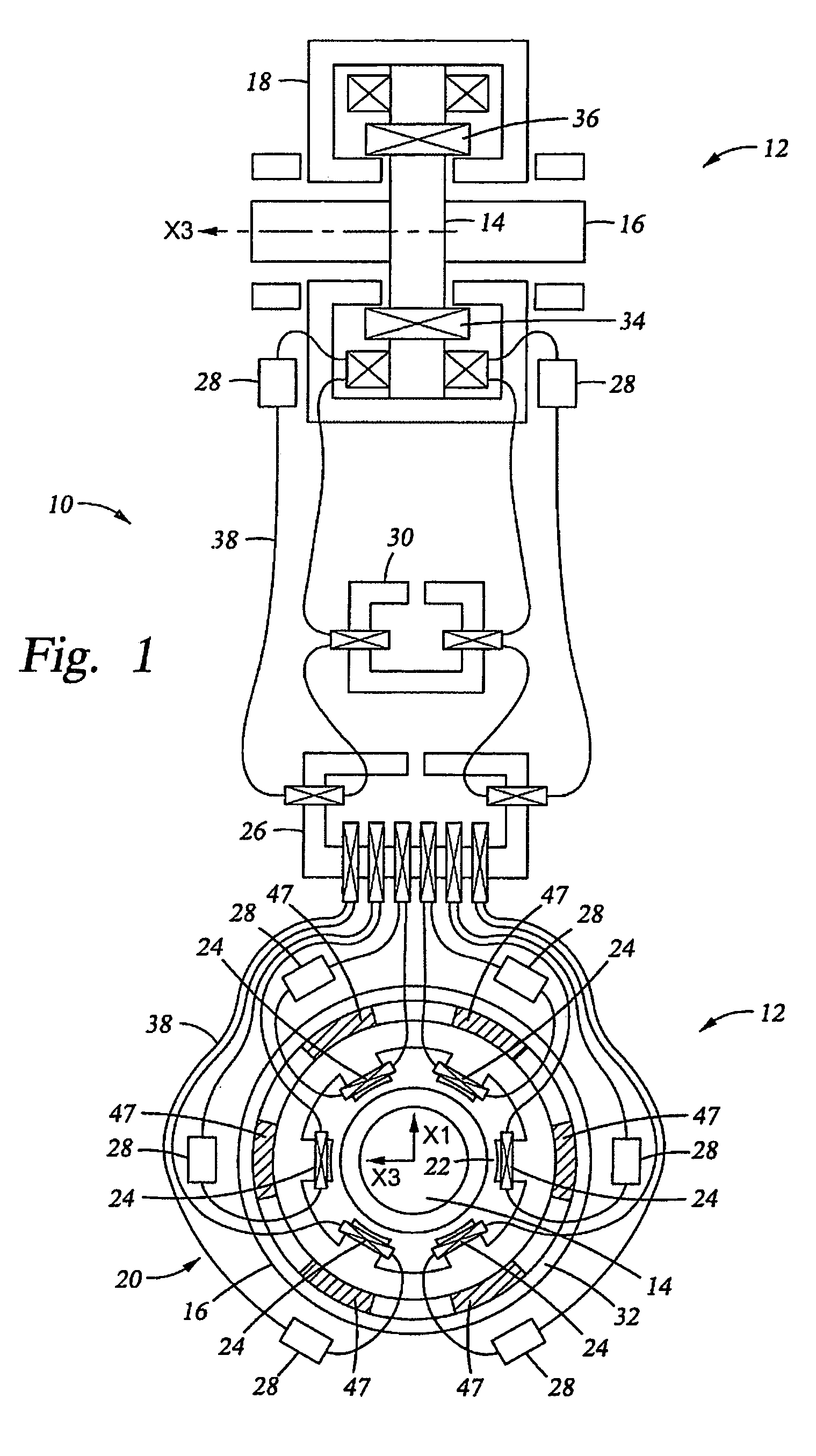
[0065]The 1D magnetic circuit model shown in FIG. 2 must be adjusted to include the effects of recirculation leakage of the flux between the N and S poles of any permanent magnet and for the effect of non-parallel (fringing) flux flow in the air gap of each pole. These adjustments are made with multiplicative factors applied to the gap flux and permanent magnetic (PM) coercive force in the 1D model, as derived from the 3D FE model. The PM coercive force is derated from 950,000 to 514,000 in the combo bearing and from 950,000 to 566,000 in the radial bearing. The air gap 22 fluxes are derated w...


PUM


Abstract

A magnetic bearing for supporting a spinning shaft in the radial direction and / or the axial direction includes a rotor formed on the shaft and a stator positioned around the rotor. Poles in the stator creates a magnetic field that supports the rotor. The number of poles is at least sufficient to produce a selected control force if there is an at least partial loss of current to one or more of the poles. The bearing also includes a set of permanent magnetic elements associated with the poles that create a homopolar, bias magnetic field. A controller connected to the poles is programmed with instructions to change the current to each pole in response to at least a partial loss of current to one or more of the poles and can include a current distribution matrix for determining a current value for each pole in such instances.

Description

CROSS-REFERENCE TO RELATED APPLICATIONS[0001]This application takes priority from U.S. Provisional Patent Application Ser. No. 60 / 576,281 filed on Jun. 1, 2004.BACKGROUND OF THE INVENTION[0002]1. Field of the Invention[0003]The invention relates generally to magnetic bearings and, in particular aspects, to the design of such bearings for resistance to magnetic coil failures.[0004]2. Description of the Related Art[0005]Bearings have a rotatable rotor and a stationary stator within which the rotor rotates. Some means of reducing friction between the rotor and stator is necessary. Magnetic bearings replace ball bearings or lubricants with a magnetic field that maintains the rotor in a spaced relation from the stator and allows the rotor to rotate in an essentially frictionless manner with respect to the stator. Magnetic bearings promise significant improvements for uses in space as, for example, storage of power in flywheels and the like. Magnetic suspensions (MS) satisfy the long life...

Claims


Application Information

Patent Timeline
Patent Type & Authority Patents(United States)
IPC IPC(8): H02K7/09
CPCF16C32/0442F16C32/0457F16C32/0444
Inventor PALAZZOLO, ALANLI, MING-HSIUKENNY, ANDREWPRUESS, JASONTUCKER, RANDALL P.PROVENZA, ANDREWBEACH, RAYMONDKASCAK, ALBERT
Owner TEXAS A&M UNIVERSITY
Why Eureka
Try Eureka