
Power transmission unit of an impactor, a hydraulic jet impactor and the application thereof

a technology of hydraulic jet and power transmission unit, which is applied in the field of rotary drilling tools, can solve the problems of premature deformation or damage of primary seals, shorten the working life of fluid-driven impactors, so as to improve the efficiency of impactors and shorten the working li

Inactive Publication Date: 2008-09-23
CHINA PETROCHEMICAL CORP +1
View PDF30 Cites 1 Cited by
  • Summary
  • Abstract
  • Description
  • Claims
  • Application Information

AI Technical Summary

Benefits of technology

[0013]One object of the present invention is to provide a fluid-driven impactor that overcomes the disadvantage of prior art such as short working life of the impactor and thereby improves the efficiency thereof.
[0014]Another object of the present invention is to provide a power transmission mechanism for the fluid-driven impactor with a higher impacting energy-transmitting efficiency.
[0015]A further object of the present invention is to provide a fluid-driven impactor that can improve the impacting energy efficiency and thereby increase the drilling speed and working efficiency by improving a power transmission mechanism.

Problems solved by technology

However, there are some disadvantages with the fluid-driven impactor and its power transmission mechanism disclosed in CN 2385068Y.
First, the abrasive members in the fluid-driven impactor need to be replaced due to the abrasion, which shortens the working life of the fluid-driven impactor.
The reason why the rubber seal ring (the primary seal) is liable to abrasion is that the flow rate of the drilling fluid passing by the seal ring is very high and the shapes of various components are irregular, which causes swirl or vortex to directly flush the seal ring abrasively.
Moreover, the primary seal prematurely degrades or damages due to the high temperature and pressure of the corrosive downhole drilling fluid and due to flush and corrosion of the main internal parts.
Therefore, the high-speed fluid easily flushes the holes abrasively.
Second, the fluid-driven impactor does not increase the drilling speed significantly, since when the impacting power is transmitted to the bit, 60% of the impacting power is lost, that is, only 40% is applied to the drilling bit.
Therefore, the working efficiency for drilling in both impacting and rotary way is greatly reduced.
Therefore, the cost for maintaining the upper fluid-diverging lids is increased yet the efficiency is not improved.
The above disadvantages can severely affect and restrain the working life and efficiency of the fluid-driven impactor, and thereby affect broad applications of the rotary-impacting drilling technique and the economic and technological benefits.

Method used


Image

  • Power transmission unit of an impactor, a hydraulic jet impactor and the application thereof
  • Power transmission unit of an impactor, a hydraulic jet impactor and the application thereof
  • Power transmission unit of an impactor, a hydraulic jet impactor and the application thereof

Examples


Embodiment Construction

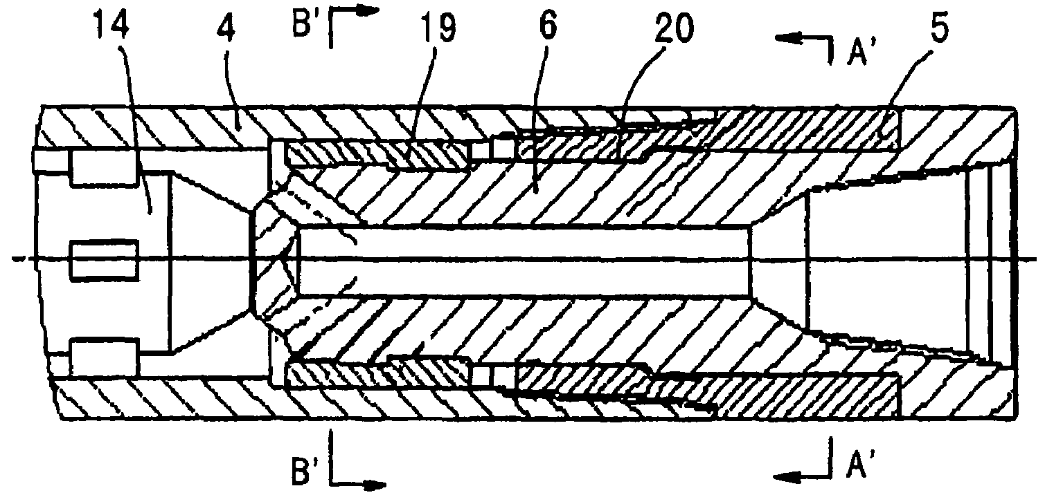
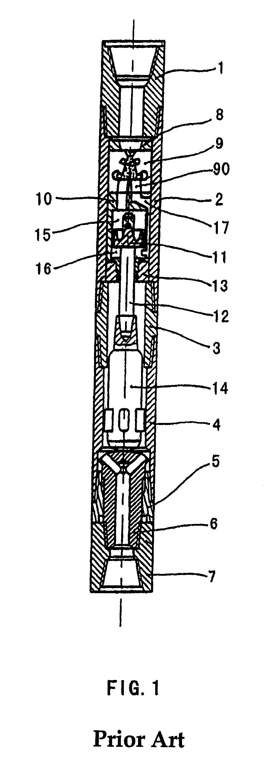
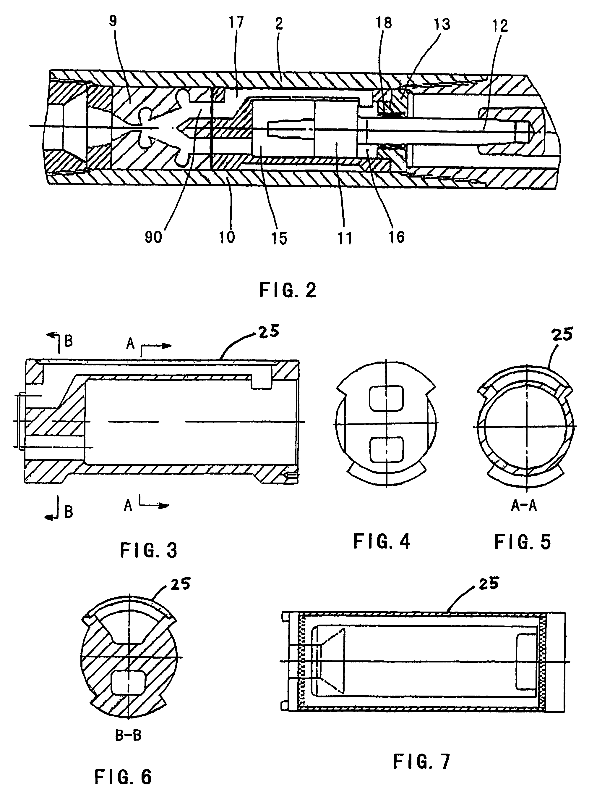
[0051]Reference will now be made in detail to the accompanying drawings to describe the preferred embodiments of the present invention. In describing the embodiments of the present invention, member or parts having the same functions as in the prior art as shown in FIG. 1 will be given the same reference numbers, and will not be described herein.

[0052]In order to provide a fluid-driven impactor without the disadvantage of short life, the improvement is made to the primary seal for the fluid-driven impactor according to one aspect of the present invention. In all aspects, the fluid-driven impactor is identical with that disclosed in CN2385068Y in terms of structure or feature or includes the improved technical features or structures of the present invention illustrated below. Therefore only members or parts related to the primary seal will be illustrated for the fluid driven impactor according to the first aspect of the present invention.

[0053]According to the first aspect of the pre...


PUM


Abstract

The invention discloses a fluid-driven impactor, a power transmission mechanism for the impactor and the use of the impactor. In the prior art, the working life of the impactor is short, since a rubber primary seal and an upper fluid-diverging lid for the fluid-driven impactor are both liable to erosion and the efficiency in transmitting power is low due to the complexity of the power transmission mechanism. In order to increase the drilling speed and / or extend the life of the impactor, the side cavity passage is formed in such a way that the inner wall of the outer pipe is isolated from the side cavity passage in a watertight manner without the use of the rubber primary seal. The loss in transmitting power is minimized by integrating the anvil of the power transmission mechanism and the lower joint. The problem of abrasion of the fluid-diverging hole is overcome and the nozzle can be used with different fluid flow by mounting a replaceable nozzle in the upper fluid-diverging lid, the nozzle selected from a series of nozzles with various inner diameters and made of a material more wearable than the material for diverging lid the upper fluid.

Description

CROSS-REFERENCE TO RELATED APPLICATIONS [0001]This application is a U.S. National Phase of PCT Application No. PCT / CN03 / 00027 filed Jan. 14, 2003, which claims priority to Chinese Application Numbers 02200714.8 and 02200716.4 filed on Jan. 14, 2002.TECHNICAL FIELD[0002]The present invention relates in general to a rotary-impacting drilling tool, and more particularly, to a power transmission mechanism, a fluid-driven impactor and its use.TECHNICAL BACKGROUND[0003]A fluid-driven impactor is one of BHA (Bottom Hole Assembly) tools powered downhole in rotary drilling processes and rotary-impacting drilling is a new process with respect to the prior art. The operation principle of the rotary-impacting drilling is as follows: a fluid-driven impactor is provided at the top of a bit or a core barrel. During the drilling, the bit rotates along with a drill string under a given bit pressure. In the meantime, the drilling bit is subjected to high frequency impacts from the impactor, such that...

Claims


Application Information

Patent Timeline
Patent Type & Authority Patents(United States)
IPC IPC(8): B23Q5/00E21B1/24E21B4/00
CPCE21B4/00
Inventor TAO, XINGHUAXU, GUOQIANGHOU, XUTIANZENG, YIJIN
Owner CHINA PETROCHEMICAL CORP
Learn More