
Information recording method and information recording apparatus that can achieve uniform signal characteristics and overwriting characteristics over an entire surface of an optical disk medium

a technology of information recording and optical disk, which is applied in the field of information recording methods and information recording apparatuses for phase change optical disk, can solve the problems of large and high-cost motors, large running torques, and long access time, and achieve the capacity of a top heating puls

Active Publication Date: 2008-09-16
RICOH KK
View PDF27 Cites 2 Cited by
  • Summary
  • Abstract
  • Description
  • Claims
  • Application Information

AI Technical Summary

Benefits of technology

The present invention provides an improved and useful information recording method and information recording apparatus that can overcome the problems of previous methods. The method and apparatus can perform recording while maintaining uniform signal characteristics over the entire surface of a phase change optical disk medium that has a recording layer. The method and apparatus can also control the emitted light volume of a laser beam during recording to be a constant value. By updating set values of the recording power and duty ratio of the erase power at predetermined intervals in accordance with the recording linear velocity, the method and apparatus can perform recording with good overwriting characteristics over an entire surface of the optical disk. The invention provides a solution for improving the recording performance of optical disks and ensuring compatibility with conventional playback-only optical disks.

Problems solved by technology

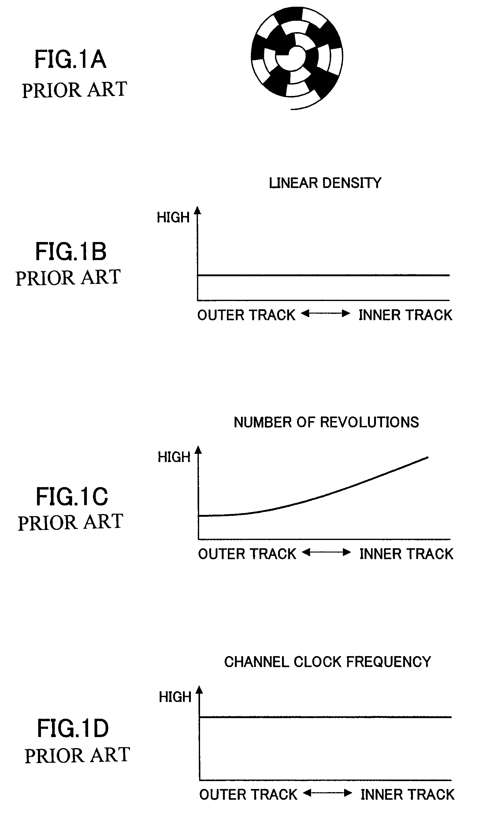
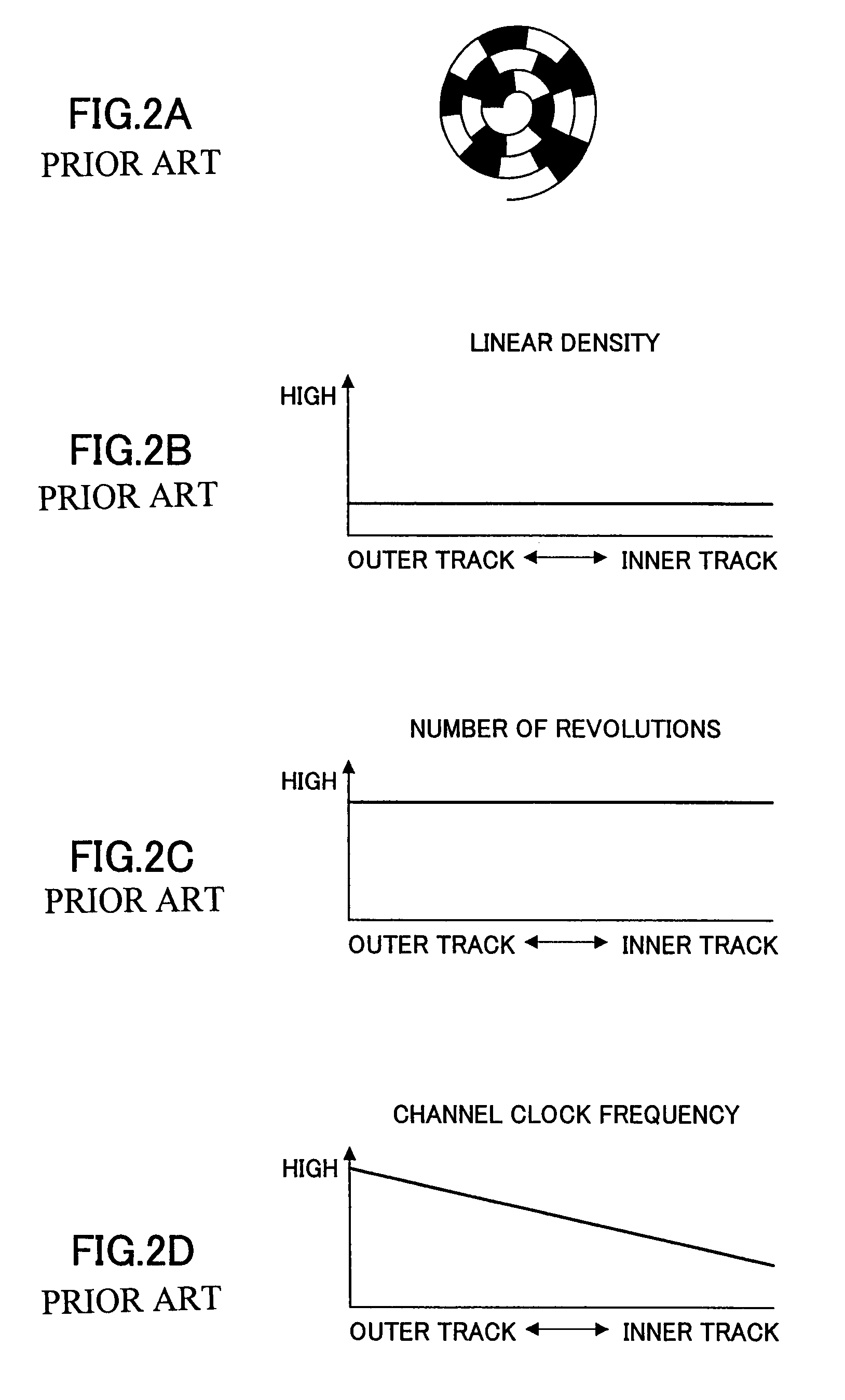
That is, a great running torque and a large and high-cost motor are required since the speed of a spindle motor for rotating the disk needs to be varied.
In addition, there is a disadvantage in that, at the time of seeking, a longer access time is required compared to that of an HDD or a MO drive, since a waiting time period is required until completion of speed variation of the spindle motor.
In other words, the heat capacity of a top heating pulse, which is necessary for formation of a mark, may be excessive or deficient, the average length of marks may be different due to variation in cooling rate, and faulty erasing and degradation of a recording film may occur due to excessive or deficient erase power.
However, generally, it is difficult for a phase change optical disk to correspond to a wide-range recording linear velocity.
Thus, there is a problem in that erase power sufficient for overwriting cannot be supplied.
However, in a recording state where the recording linear velocity is not constant as in CAV recording, it is difficult to perform recording in which uniform signal characteristics are obtained over the entire surface of a disk and a decrease in the number of times of overwriting is prevented.
However, merely qualitative effects with respect to an optical disk medium are obtained, which are not sufficient for recording disks, particularly, for DVDS.
In other words, since variation in overwriting characteristics, i.e., variation in characteristics of recording information (RF signal) such as a decrease in the number of times of overwriting, is not only affected by formation of a recording mark part but also by the light emission waveform of an erasing pulse part in an interacting manner, the recording methods disclosed in the above-mentioned patent documents are not sufficient, and it is not always possible to obtain uniform signal characteristics over the entire surface of an optical disk and to avoid a decrease in the number of times of overwriting.
Thus, it is not always possible to obtain desired effects at a high recording linear velocity covering a wide range.
Moreover, even if the set values of an erasing pulse part are to be varied, quantitative study has not been conducted with respect to how to vary the set values.

Method used


Image

  • Information recording method and information recording apparatus that can achieve uniform signal characteristics and overwriting characteristics over an entire surface of an optical disk medium
  • Information recording method and information recording apparatus that can achieve uniform signal characteristics and overwriting characteristics over an entire surface of an optical disk medium
  • Information recording method and information recording apparatus that can achieve uniform signal characteristics and overwriting characteristics over an entire surface of an optical disk medium

Examples


first embodiment

[0091]Referring to FIGS. 3A through 8, a description is given below of the present invention.

[0092]As shown in FIG. 3B, in a basic recording pulse sequence used in a phase change optical disk, which is an optical disk medium, the pulse width is set by: a top heating pulse duty ratio Ttop of the top heating pulse constituting a recording pulse sequence; a duty pulse Tmp of a heating pulse in a multi-pulse part following the top heating pulse; and an end-off cooling pulse duty ratio Tecp of the end-off cooling pulse of the recording pulse sequence. In addition, recording power is set by heating power Pw, erase power Pe0, and bias power Pb. With respect to the recording power, since the state of mark formation is affected not only by the erase power Pe0 but also by the heating power Pw in an interacting manner, an erase power ratio ε0 (=Pe0 / Pw) of the erase power Pe0 to the heating power Pw is set. In this embodiment, as shown in FIGS. 3C and 3D, a heating pulse (erasing pulse) in an e...

second embodiment

[0117]Referring to FIG. 8, a description is given below of the present invention.

[0118]Generally, a wobbled groove is formed on a phase change optical disk for obtaining a tracking error signal (push-pull signal). Wobble signals obtained from the wobble of the groove are superimposed. Each of the wobble signals is detected by a programmable BPF (Band Pass Filter) at each recording linear velocity, as is described below. The wobble signals include address information coded by frequency modulation or phase modulation. By demodulating the address information, it is possible to obtain as the pre-format information the address information and disk information that are inherent to a disk even from an unrecorded disk. A method is also known in which such information is generated from intermittent pits (Land Pre-Pit signal) provided in a land portion of a disk.

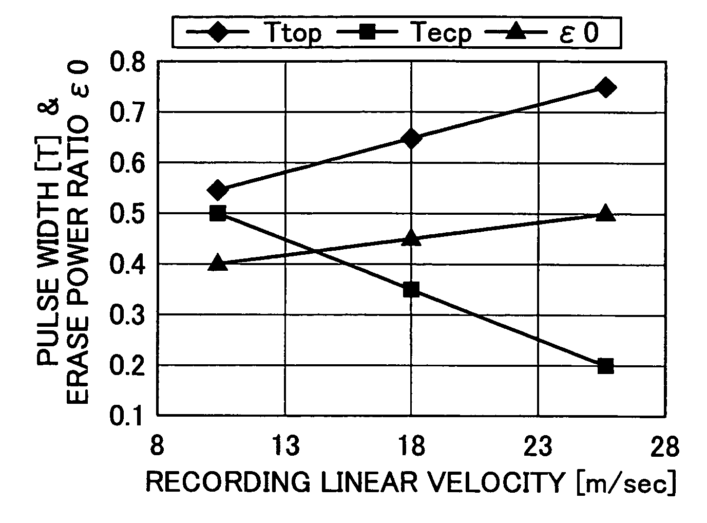
[0119]The optimum top heating pulse duty ratio Ttop, the end-off cooling pulse duty ratio Tecp, the erase power ratio ε0, the erase ...

third embodiment

[0125]Referring to FIG. 10, a description is given below of the present invention. This embodiment relates to an information recording apparatus for performing recording on a phase change optical disk medium 1 by using the information recording method in which the set values of the duty ratio Te1 of the width of an erasing pulse and the erase powers Pe1 and Pe2 for dividing the erasing pulse part (space part) into multiple pulses are updated in accordance with the variation in the recording linear velocity.

[0126]FIG. 10 is a block diagram showing an information recording apparatus 100 according to the third embodiment of the present invention.

[0127]The information recording apparatus 100 includes: a spindle motor 2, a rotation mechanism 3, an optical head 5; an actuator mechanism 6; a servo mechanism 7; a wobble detector 9; an address demodulation circuit 10; a recording clock generator 12; a drive controller 13; a system controller 14; an EFM encoder 15; an erasing pulse sequence c...


PUM

PropertyMeasurementUnit
diameteraaaaaaaaaa
frequencyaaaaaaaaaa
frequencyaaaaaaaaaa

Abstract

In an information recording method and apparatus, when performing recording by using multiple pulses defined by erase powers Pe1 and Pe2 for forming a space part between mark parts, the set values of the erase powers Pe1 and Pe2 are updated at predetermined intervals in accordance with a recording linear velocity.

Description

BACKGROUND OF THE INVENTION[0001]1. Field of the Invention[0002]The present invention generally relates to information recording methods and information recording apparatuses for phase change optical disks such as DVD-RWs (ReWritable), which include a recording layer whose phase is reversibly changed between a crystal phase and an amorphous phase and are compatible with the formats of, for example, DVD-Videos (Digital Videos or Digital Versatile Discs) and playback-only DVDs such as DVD-ROMs.[0003]2. Description of the Related Art[0004]With the penetration of multi-media, various information recording disks have been developed: examples include playback-only disks such as DVD-Videos and DVD-ROMs, recordable DVD-Rs using an organic dye material for a recording layer, and rewritable DVD-RWs using a phase change material for a recording layer.[0005]Information (sectors, in this example) recorded on such DVDs is in the format shown in FIG. 1A. In such a format, data (sectors) are contin...

Claims


Application Information

Patent Timeline
Patent Type & Authority Patents(United States)
IPC IPC(8): G11B5/09G11B7/0045G11B7/006G11B7/125G11B7/1263
CPCG11B7/1263G11B7/0062
Inventor YOKOI, KENYA
Owner RICOH KK
Learn More