
Interleaved soft switching bridge power converter

a power converter and soft switching technology, applied in the direction of electric variable regulation, process and machine control, instruments, etc., can solve the problems of prohibitively high switching losses, limited operating frequencies of switch mode power supplies that utilize hard-switching power converters, and reduce the energy that can be supplied to plasma arcs, etc., to reduce the loss of switching turn on and diode reverse recovery, the effect of reducing the loss of switching

Inactive Publication Date: 2008-09-09
ADVANCED ENERGY IND INC
View PDF12 Cites 51 Cited by
  • Summary
  • Abstract
  • Description
  • Claims
  • Application Information

AI Technical Summary

Benefits of technology

This approach enables efficient high-frequency operation with reduced switching losses, suitable for high-power and high-voltage applications such as plasma processing, active rectifiers, and motor drive inverters, by minimizing energy delivery to plasma arcs and optimizing power waveform control.

Problems solved by technology

High-frequency operation allows the use of smaller output filter capacitors, which store less energy than larger capacitors, and this reduces the energy that can be supplied to plasma arcs.
Operating frequencies in switch mode power supplies that utilize hard-switching power converters are limited, however, because the switching losses can become prohibitively high as the operating frequency is increased.
In hard-switched converter circuits, however, considerable losses may occur when an active switch in a simple pole circuit is turned on while a diode in the other switch of the pole circuit is conducting.
In addition to requiring auxiliary switches, such soft-switching bridge schemes typically include resonant circuits that add additional cost and incur losses due to circulating currents.
The poles circuits are switched in an interleaved manner that reduces ripple in the output current, but the circuit does not provide soft switching.
The active switches in the positive and negative pole circuits are both on at the same time, and so considerable current flows in these inductors even when there is no output current, resulting in low efficiencies.

Method used


Image

  • Interleaved soft switching bridge power converter
  • Interleaved soft switching bridge power converter
  • Interleaved soft switching bridge power converter

Examples


Embodiment Construction

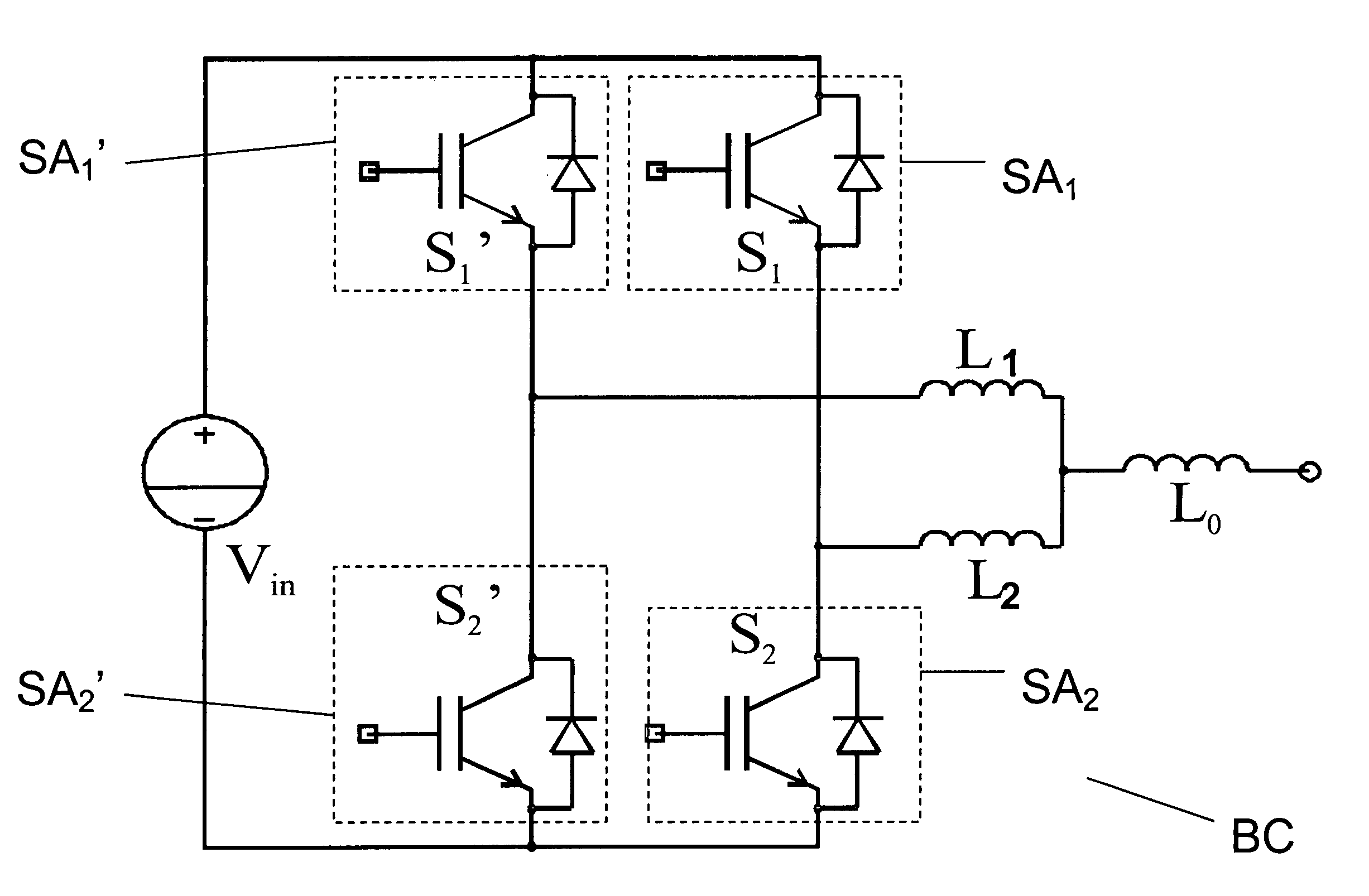
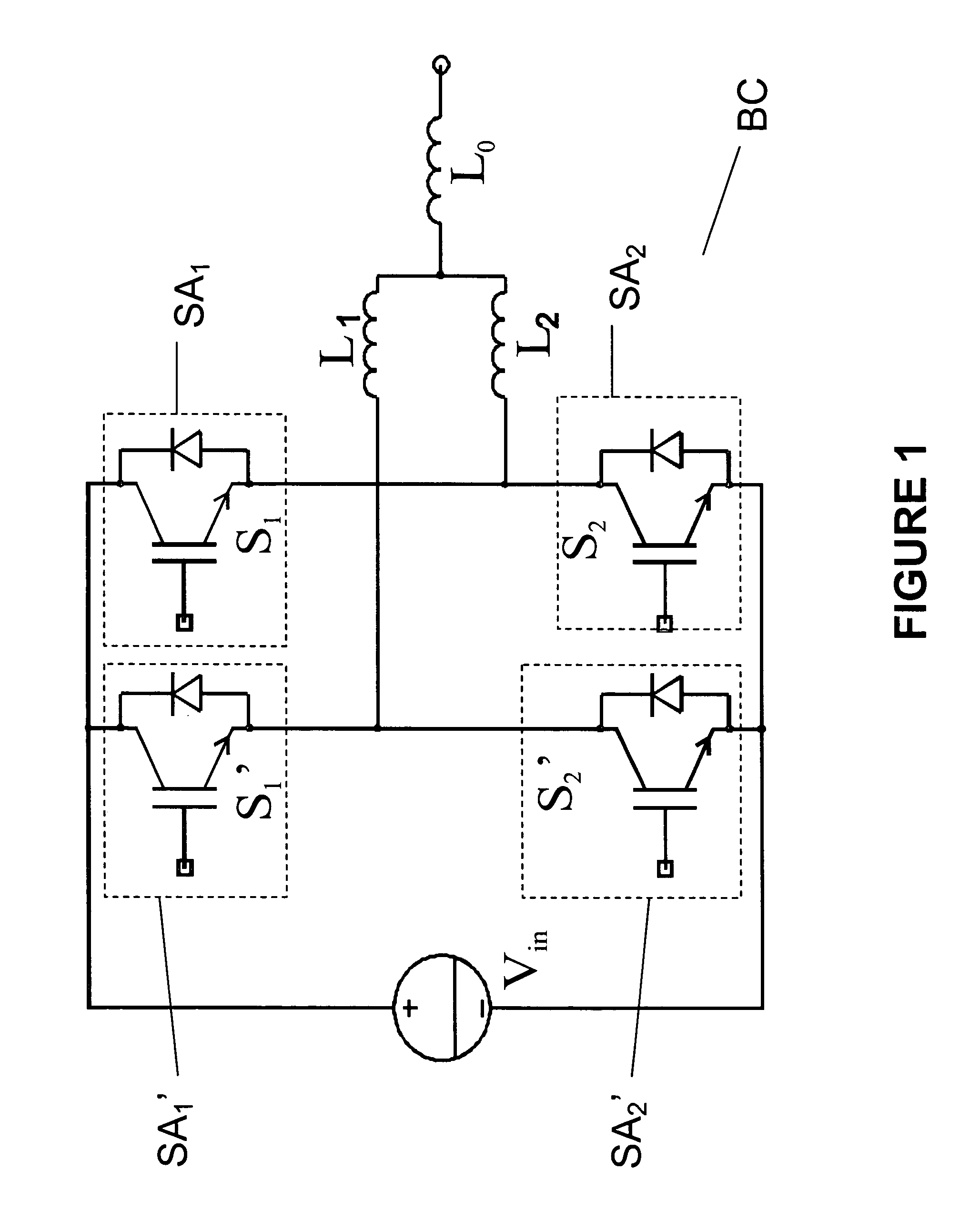
[0022]FIG. 1 illustrates an interleaved soft switching circuit in accordance with one embodiment of the invention. Bridge converter circuit BC comprises switching pole circuits comprising switch assemblies SA1, SA1′, SA2, and SA2′. Each of switch assemblies SA1, SA1′, SA2, and SA2′ comprises a switching semiconductor switching device S1, S1′, S2, and S2′, respectively, disposed in parallel with an anti-parallel diode. Switches S1′ and S2′ and switches S1 and S2 form first and second pole circuits, respectively, disposed across positive and negative voltages supplied by voltage supply Vin. Control circuitry (not shown) is connected to the control terminals of switches S1, S1′, S2, and S2′ and delivers control pulses to control opening and closing of the switches. First pole circuit comprising switches S1′ and S2′ has an active pole terminal connected to inductor L1, and second pole circuit comprising switches S1 and S2 has an active pole terminal connected to inductor L2. The outputs...


PUM


Abstract

An interleaved soft switching bridge power converter comprises switching poles operated in an interleaved manner so as to substantially reduce turn-on switching losses and diode reverse-recovery losses in the switching pole elements. Switching poles are arranged into bridge circuits that are operated so as to provide a desired voltage, current and / or power waveform to a load. By reducing switching turn on and diode reverse recovery losses, soft switching power converters of the invention may operate efficiently at higher switching frequencies. Soft switching power converters of the invention are well suited to high power and high voltage applications such as plasma processing, active rectifiers, distributed generation, motor drive inverters and class D power amplifiers.

Description

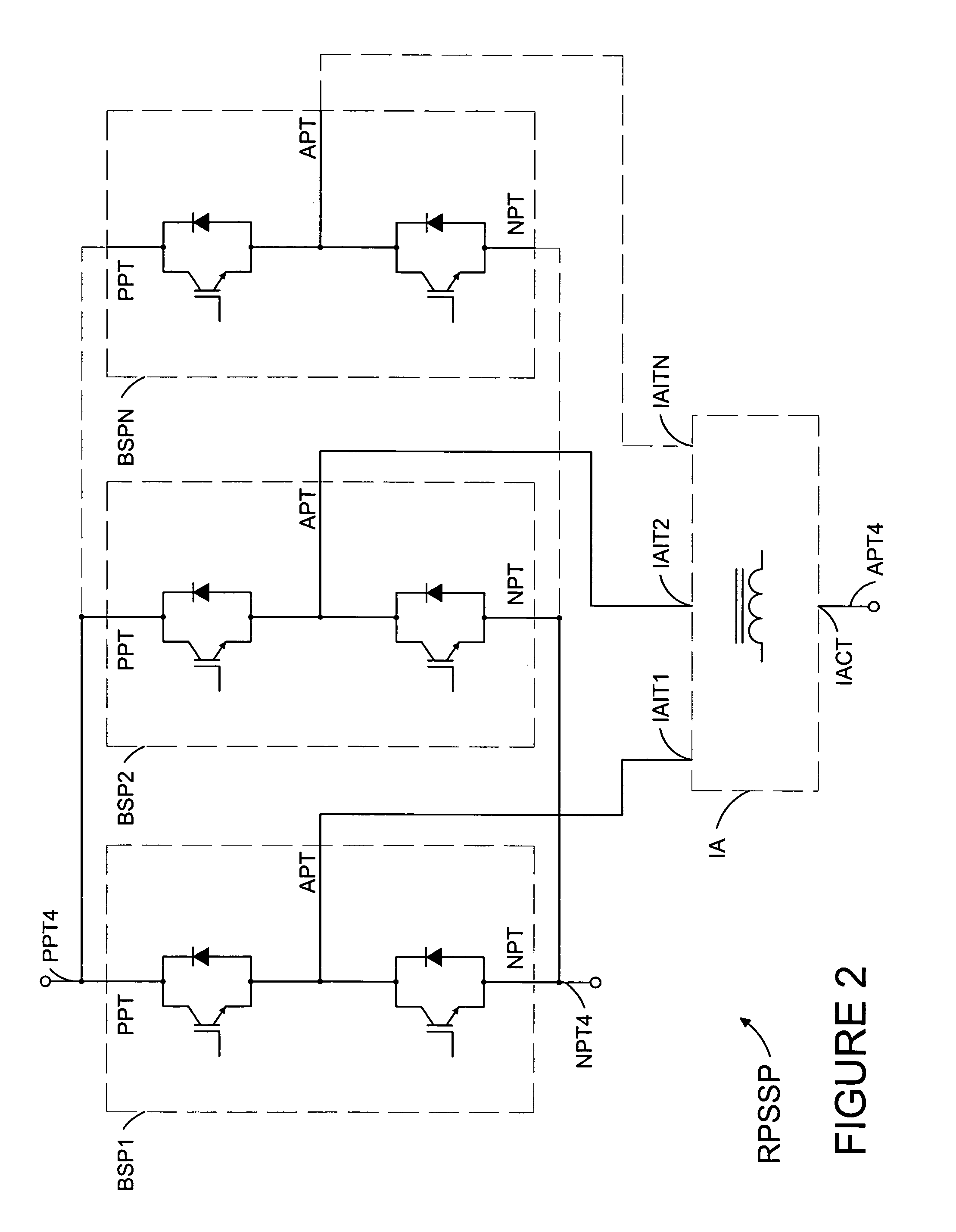
BACKGROUND OF THE INVENTION[0001]1. Field of the Invention[0002]This invention relates generally to switch mode power converters, and more particularly, though not by way of limitation, to soft switching bridge power converters suitable for high power and high voltage DC-DC, AC-DC and DC-AC conversion.[0003]2. Brief Description of the Prior Art[0004]It is generally desirable to operate switching power supplies at the highest frequency that is practical for a particular circuit. Operating at higher frequencies allows inductor and capacitor values in a power supply to be reduced, which reduces physical size and cost and also enables improvements in the transient response of the power supply. Reducing the energy available for delivery to load arcing, such as plasma arcs, is also a desirable goal. High-frequency operation allows the use of smaller output filter capacitors, which store less energy than larger capacitors, and this reduces the energy that can be supplied to plasma arcs. Op...

Claims


Application Information

Patent Timeline
Patent Type & Authority Patents(United States)
IPC IPC(8): H02M7/5387H02M3/24H02M7/00
CPCH02M3/1584H03F3/217H02M7/493H02M3/1586H02M1/0043H02M3/335
Inventor ILIC, MILAN
Owner ADVANCED ENERGY IND INC
Learn More