
Sliding door arrangement for a motor vehicle

a technology for sliding doors and motor vehicles, applied in the direction of doors, lock applications, roofs, etc., can solve the problems of small holding forces needed for this purpose, and achieve the effects of high crash safety, economical structure, and great ease of us

Inactive Publication Date: 2008-09-09
BROSE SCHLIESSSYSTEME GMBH & CO KG
View PDF16 Cites 14 Cited by
  • Summary
  • Abstract
  • Description
  • Claims
  • Application Information

AI Technical Summary

Benefits of technology

The present invention is a sliding door arrangement that combines high crash safety with ease of use. It achieves this by using a catch lever that can fix the sliding door in both the opened and closed positions, with the catch lever pretensioned in the closed position to ensure maximum reliability in the event of a crash. The catch lever is designed to be easily raised with minimal force when the sliding door is opened, but to provide maximum pretensioning when the sliding door is in the closed position. The lock arrangement includes a main lock arrangement and an auxiliary lock arrangement to support the main lock arrangement, with the latch elements latch and ratchet assigned to the auxiliary lock arrangement. The invention is compact, economical, and effective in ensuring safety and ease of use.

Problems solved by technology

Furthermore, the holding forces necessary for this purpose are small.

Method used


Image

  • Sliding door arrangement for a motor vehicle
  • Sliding door arrangement for a motor vehicle
  • Sliding door arrangement for a motor vehicle

Examples


Embodiment Construction

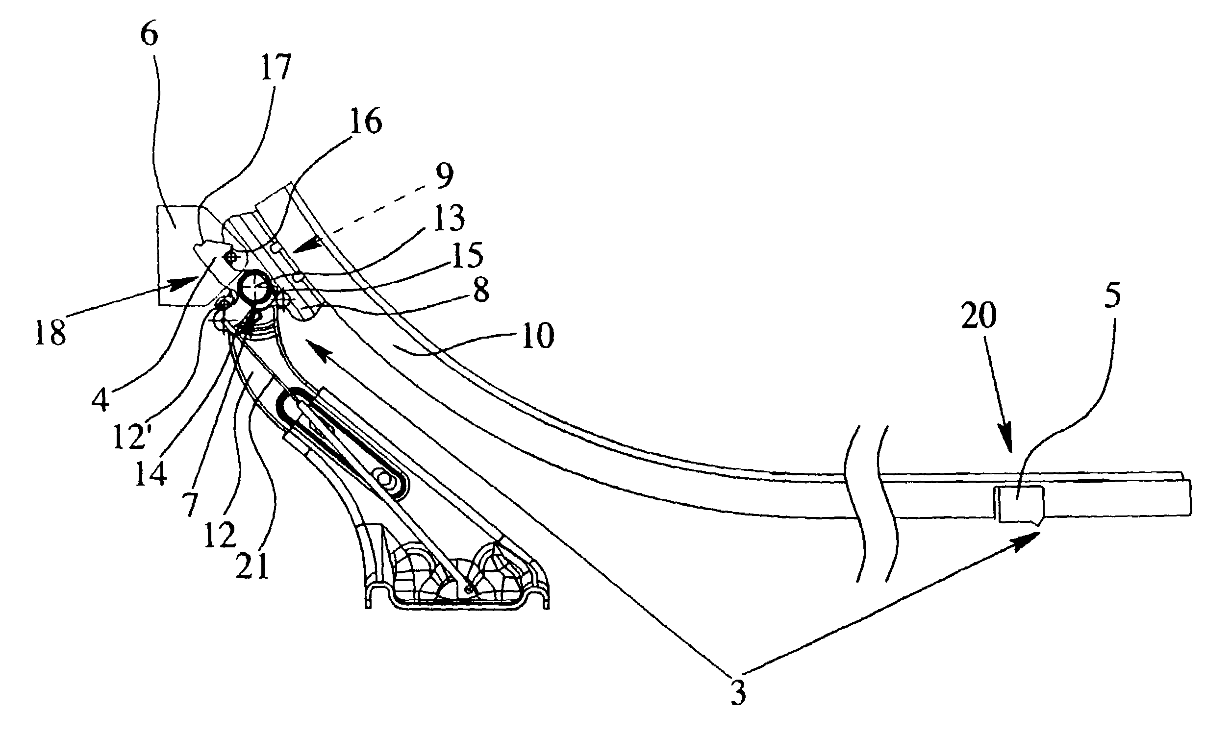
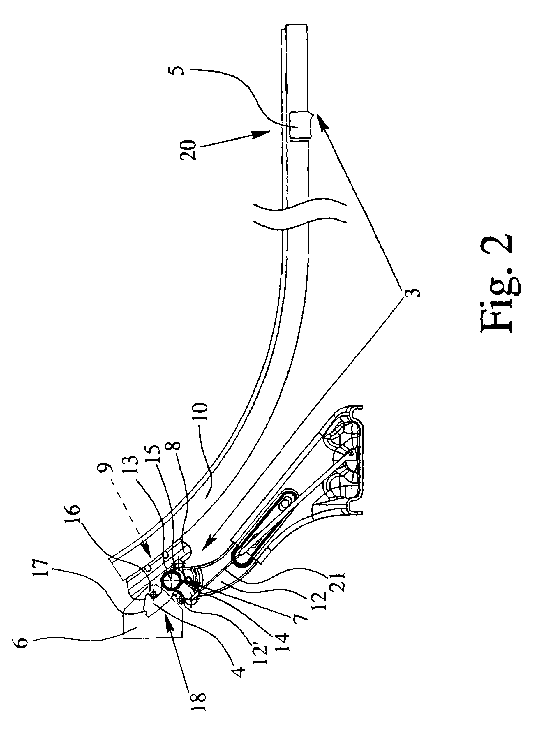
[0032]In the drawings, FIG. 1 shows a motor vehicle with a sliding door arrangement which is located laterally on the vehicle. It is also equally possible for the sliding door arrangement to be located on the back of the motor vehicle. The sliding door arrangement has a sliding door 1 which can be moved by a sliding motion into an opened position (shown in FIG. 1 in broken lines) and into a closed position (shown in FIG. 1 in solid lines). The configuration of the guide of the sliding door 1 is detailed below.

[0033]To fix the sliding door 1 in the opened position, on the one hand, and in the closed position, on the other hand, there is a lock arrangement 2. Basically, the lock arrangement 2 can also be used to fix the sliding door 1 in the intermediate position.

[0034]The lock arrangement 2 is equipped here with a catch lever arrangement 3 which has a pivoting catch lever 4. The catch lever 4 can be moved into the engaged state (FIG. 2, FIG. 4) and into the raised state (FIG. 3). The...


PUM


Abstract

Sliding door arrangement for a motor vehicle having a lock arrangement, for fixing a sliding door in opened and closed positions, with a catch lever arrangement with a pivoting catch lever that is movable into engaged and raised states and is pretensioned toward the engaged state. The catch lever arrangement has first and second engagement elements with which the catch lever engageable, the catch lever, when the sliding door is in the opened position, engaging the first engagement element and the catch lever fixing the sliding door in the opened position. The catch lever is engageable with the second engagement element when the sliding door is in the closed position and the catch lever fixes the sliding door in the closed position. The arrangement is such that the pretensioning of the catch lever toward the engaged state rises by the movement of the sliding door into the closed position.

Description

BACKGROUND OF THE INVENTION[0001]1. Field of the Invention[0002]This invention relates to a sliding door arrangement for a motor vehicle in which the sliding door is slidable into opened and closed positions, and in which a lock arrangement is provided for fixing the sliding door in the opened and in the closed position, the lock arrangement having a catch lever arrangement, the catch lever arrangement having a pivoting catch lever, the catch lever being movable into an engaged state and into a raised state and being pretensioned into the engaged state, the catch lever arrangement having a first engagement element and a second engagement element which the catch lever engages in an engaged state, the catch lever, when the sliding door is in the opened position being able to engage the first engagement element and the catch lever which is then in the engaged state fixing the sliding door in the opened position.[0003]The invention is also directed to a sliding door arrangement for a mo...

Claims


Application Information

Patent Timeline
Patent Type & Authority Patents(United States)
IPC IPC(8): B60J5/06
CPCB60J5/06E05B65/0852E05C17/62E05B79/20E05B83/40E05D15/1047Y10S292/23E05Y2900/531
Inventor KOTHE, MARKUSHOERSCHGEN, FRANK
Owner BROSE SCHLIESSSYSTEME GMBH & CO KG
Learn More