
Flexible buoy

a buoy and flexible technology, applied in the field of flexible buoys, can solve the problems of recessed buoys, damaged buoys, damaged objects on working boats, etc., and achieve the effect of excellent workability and excellent durability

Inactive Publication Date: 2008-09-09
THE YOKOHAMA RUBBER CO LTD
View PDF15 Cites 1 Cited by
  • Summary
  • Abstract
  • Description
  • Claims
  • Application Information

AI Technical Summary

Benefits of technology

The flexible buoy provides improved workability, durability against collisions, and resistance to corrosion, allowing for easy storage and maintenance, maintaining desired buoyancy in deep water without permanent deformation.

Problems solved by technology

However, because the steel buoy has stiffness while being a heavy load, there have been a lot of problems that the working boat, and an object on the working boat are damaged when the steal buoy is in contact with them and that the buoys occupy a space on the working boat.
Additionally, because the steel buoy does not have shock-absorbing properties, it have often happed that, when the steel buoy collides with another object, the buoy itself becomes recessed and damaged.
Moreover, when the steel buoy is used in a water zone with a depth deeper than a specified depth, by mistake, the buoy sometimes crushes due to a hydraulic pressure.
Once the steel buoy has thus crushed, collection of the steel buoy becomes difficult.
In addition, even if the steel buoy is collected, it is impossible to reuse the steel buoy because an original form thereof cannot be restored.
Furthermore, because steel which is material for the steel buoy is corrosive, while the buoy is being placed in the water, the buoy should be disembarked at regular intervals to be treated with maintenance for corrosion prevention, or to be replaced in some situations.

Method used


Image

  • Flexible buoy
  • Flexible buoy
  • Flexible buoy

Examples


Embodiment Construction

[0022]Hereinbelow, embodiments of the present invention will be described with reference to the accompanying drawings.

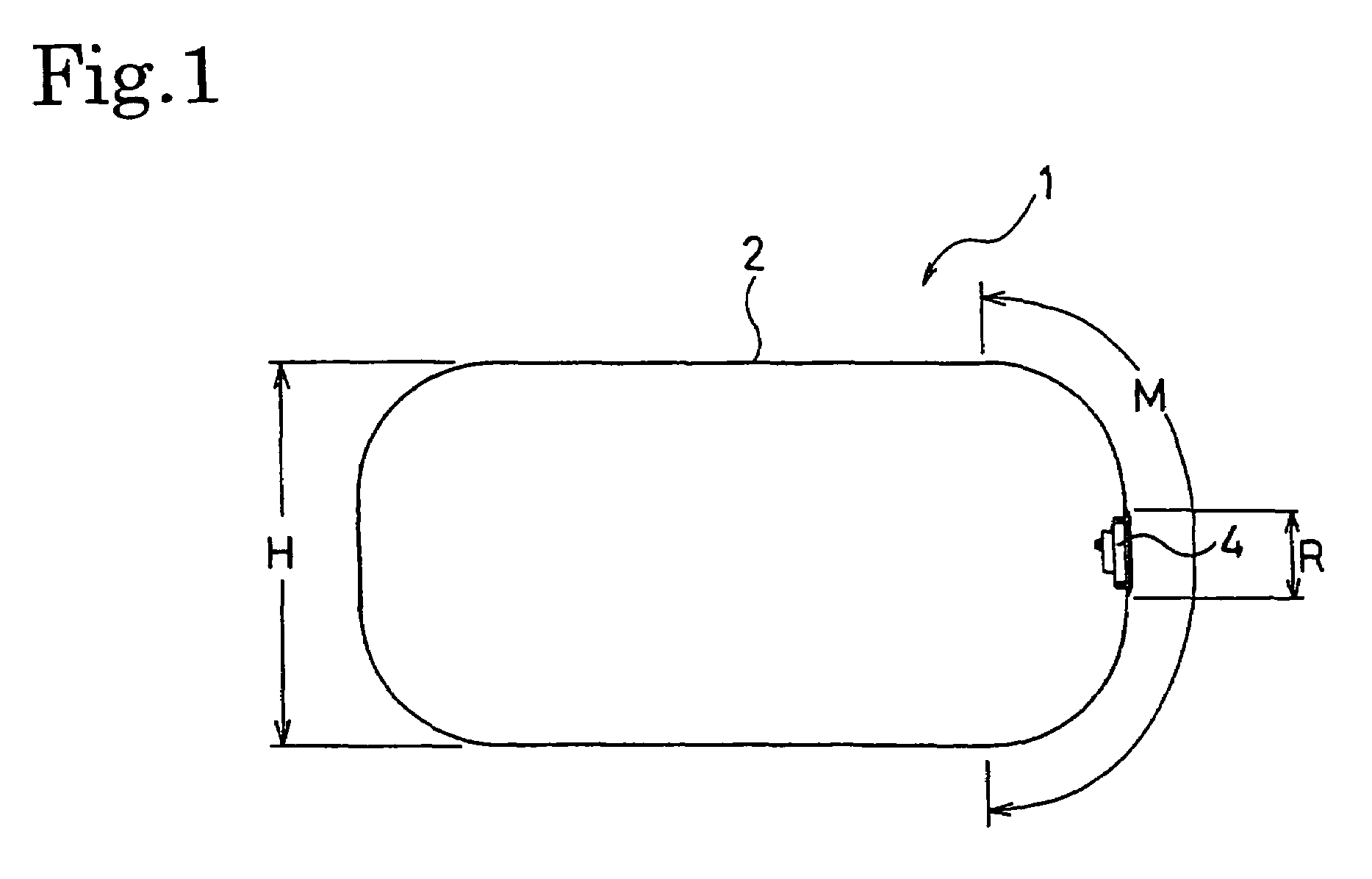
[0023]FIG. 1 is an explanatory diagram showing a cross-sectional profile of one embodiment of a flexible buoy of the present invention.

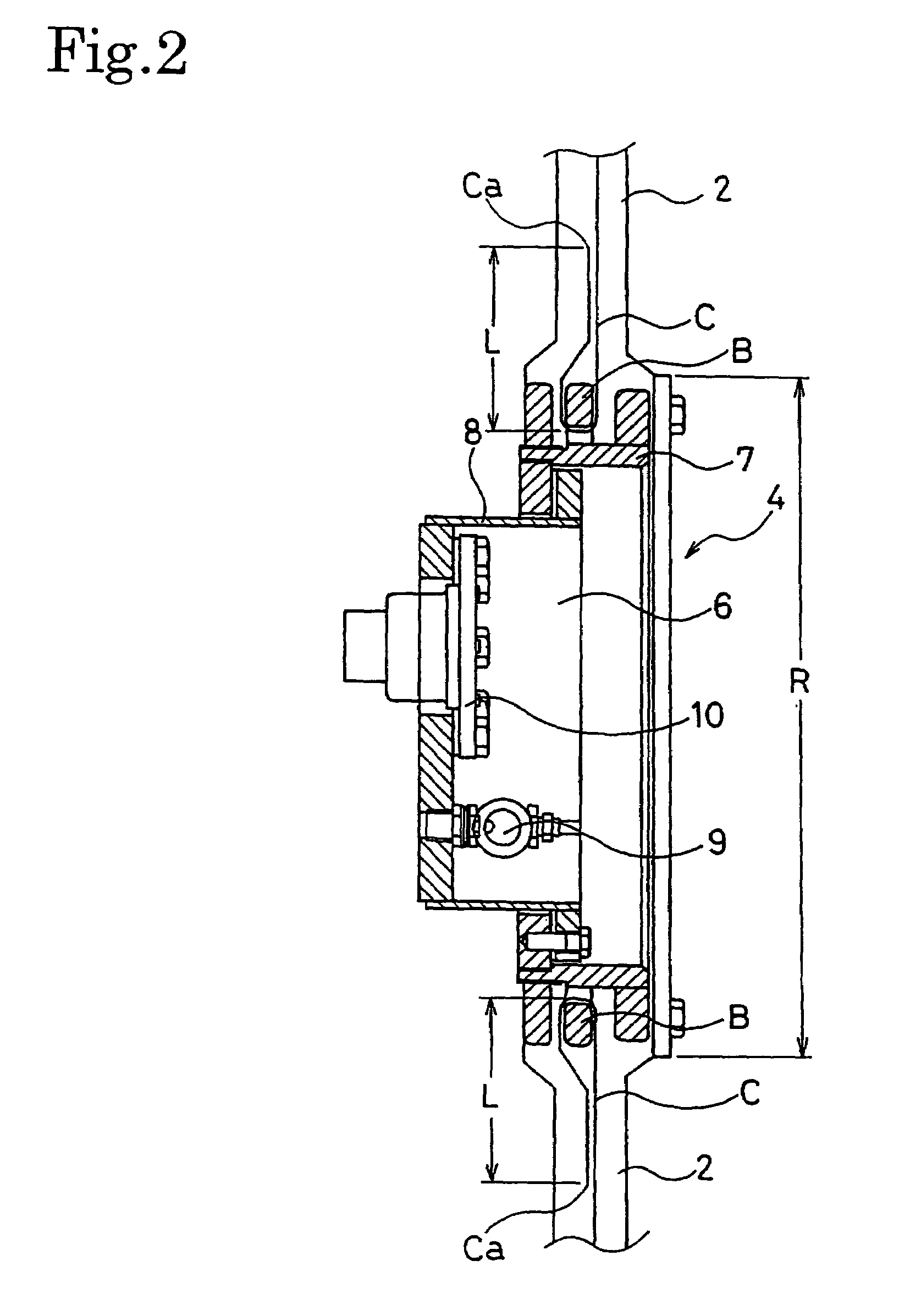
[0024]In FIG. 1, a flexible buoy 1 is constituted of a flexible membrane which is made of rubber or resin, which includes a reinforcement layer C (refer to FIG. 2) buried therein. The flexible buoy 1 is formed as an airtight hollow structure 2 to which a flange opening 4 having a gas inlet is provided. Since the hollow structure 2 is constituted of the flexible membrane made of the rubber or the resin, the hollow structure 2 is characterized by being lightweight, and by being foldable in a state that it is deflated.

[0025]This flexible buoy 1 is used in the water or on the water. The internal pressure of the highly airtight hollow structure 2 can be controlled by having a gas, such as air, injected into or discharged from the hollow st...


PUM

PropertyMeasurementUnit
intersecting angleaaaaaaaaaa

Abstract

Provided is a flexible buoy lightweight, excellent in workability, and excellent in durability preventing the buoy from being damaged by contact and collision with another object. An airtight hollow structure (2) is formed of a flexible membrane made of rubber or resin, in which a reinforcement layer (C) is buried. A flange opening (4) having a gas inlet is fixed to at least one position of the hollow structure (2). Buoyancy thereof can be controlled by using an internal pressure of a gas injected in the hollow structure (2).

Description

TECHNICAL FIELD[0001]The present invention relates to a flexible buoy. More specifically, the present invention relates to a flexible buoy configured to enhance workability of placing and removing mooring rope and the like of a rig in water.BACKGROUND ART[0002]In general, a steel buoy is used as a mooring buoy which is used for placing and removing mooring rope of an oil drilling rig or the like in an offshore area (for example, refer to Patent Document 1). However, because the oil drilling rig is moved with a change of places for drilling, at every time of the movement, construction for placing and removing an anchor, mooring rope and the mooring buoy is repeatedly carried out. Additionally, at every time of the movement, the above steel buoys are piled on a working boat and the buoys are unloaded at the next place for drilling.[0003]However, because the steel buoy has stiffness while being a heavy load, there have been a lot of problems that the working boat, and an object on the ...

Claims


Application Information

Patent Timeline
Patent Type & Authority Patents(United States)
IPC IPC(8): B63B59/02B63B5/24B63B22/18B63B22/22B63B27/36
CPCB63B22/22B63B5/24B63B2231/52B63B2231/44B63B22/18B63B27/36
Inventor WAKABAYASHI, MASASHIKANEKO, MICHITO
Owner THE YOKOHAMA RUBBER CO LTD
Learn More