Self oscillating inrush current limiting converter

a self-oscillating, inrush current technology, applied in the direction of electric variable regulation, process and machine control, instruments, etc., can solve the problems of high dissipation of resistive inrush limiters and failures

Active Publication Date: 2008-09-02
SL POWER ELECTRONICS
View PDF19 Cites 3 Cited by
  • Summary
  • Abstract
  • Description
  • Claims
  • Application Information

AI Technical Summary

Problems solved by technology

However, if the line keeps recycling, then the resistive inrush limiter suffers high dissipation and failures could occur.

Method used


Image

  • Self oscillating inrush current limiting converter
  • Self oscillating inrush current limiting converter
  • Self oscillating inrush current limiting converter

Examples


Embodiment Construction

[0018]Throughout this description, the embodiments and examples shown should be considered as exemplars, rather than limitations on the apparatus and methods disclosed or claimed.

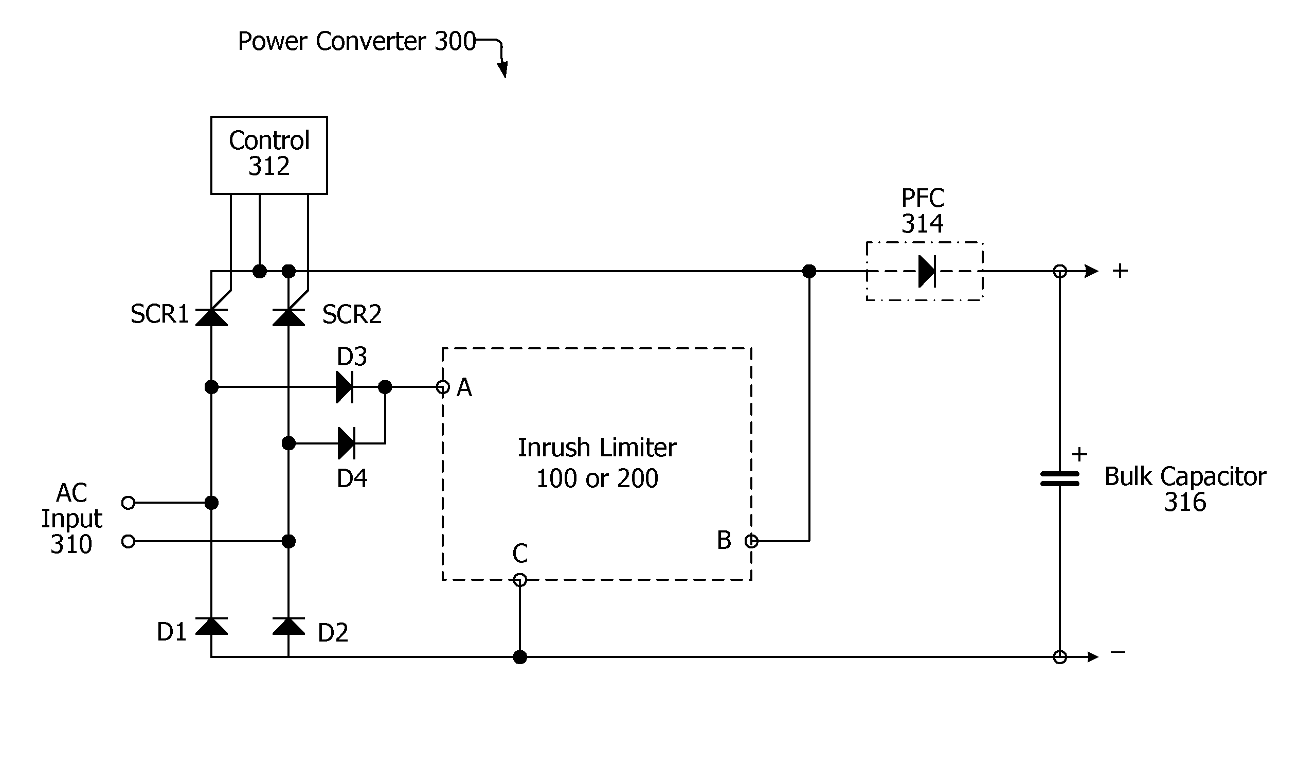
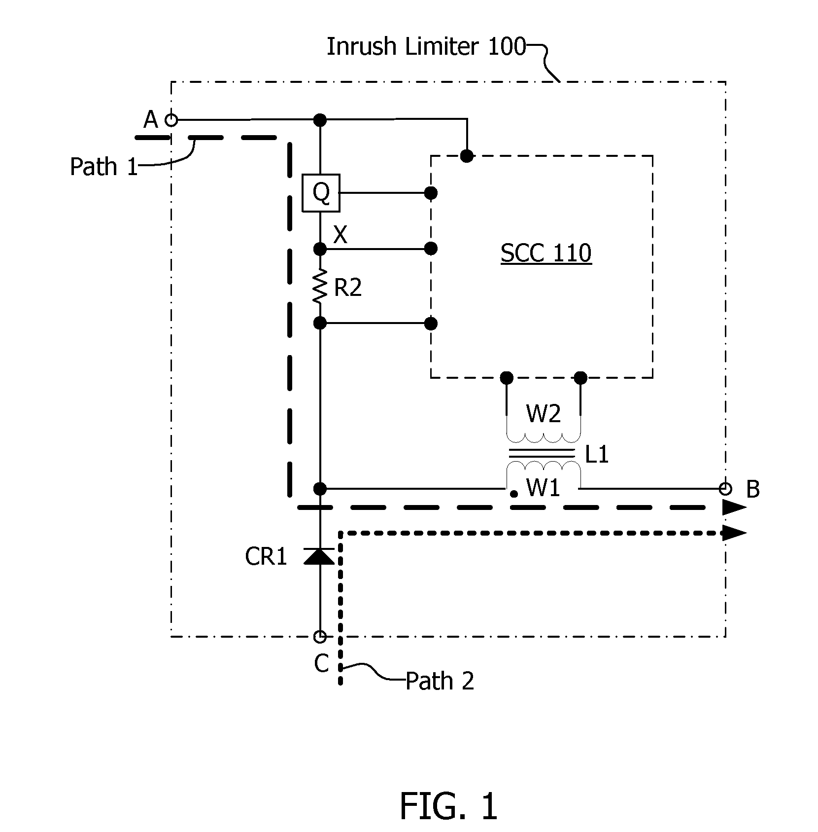
[0019]Referring to FIG. 1, the inrush limiter 100 includes a terminal A, a terminal B and a terminal C. Terminal A is an input normally connected to a power source, terminal B is an output normally connected to a load, and terminal C is a common connection for the return of the power source and load. Current passes through terminal A and exits at terminal B. The inrush limiter 100 includes a switch Q, a current sense resistor R2, windings W1 and W2 on either side of a power inductor L1, a rectifier CR1, and a sensing control circuit (SCC) 110. Switch Q may be a bipolar NPN transistor, FET switch, a MOSFET, and an insulated gate bipolar transistor (IGBT).

[0020]The switch Q, the primary winding W1 on power inductor L1, and the rectifier CR1 may be connected in a configuration similar to that commonly known as...


PUM


Abstract

There is disclosed a power converter having limited inrush current and an inrush current limiter circuit. The inrush limiting circuit may be a self-oscillating switching-mode average current regulator tp provide a relatively constant average charging current to a bulk capacitor until the bulk capacitor is fully charged. A bypass switch may be used to route current around the inrush current limiter circuit once the bulk capacitor is fully charged.

Description

NOTICE OF COPYRIGHTS AND TRADE DRESS[0001]A portion of the disclosure of this patent document contains material which is subject to copyright protection. This patent document may show and / or describe matter which is or may become trade dress of the owner. The copyright and trade dress owner has no objection to the facsimile reproduction by anyone of the patent disclosure as it appears in the Patent and Trademark Office patent files or records, but otherwise reserves all copyright and trade dress rights whatsoever.BACKGROUND[0002]1. Field[0003]This disclosure relates to power supplies having high inrush currents incurred during initial AC turn on and during power cycling.[0004]2. Description of the Related Art[0005]The charging of a bulk capacitor during start-up of an off-line AC / DC power supply generates a surge current also known as an inrush current. The impact of inrush current can be mitigated in various ways. The techniques of reducing the impact of an inrush current are often...

Claims


Application Information

Patent Timeline
Patent Type & Authority Patents(United States)
IPC IPC(8): H02M7/155G05F1/613
CPCH02M7/125H02M7/062Y10S323/908
Inventor INGMAN, THOMAS M.
Owner SL POWER ELECTRONICS
Why Eureka
Try Eureka