
Optical system with iris controlled in real time

a technology of optical system and iris control, applied in the field of optical system, can solve the problems of limited c/r of projection optical system or dmd panel, inability to continuously increase c/r, and inability to partially increase or decrease the amount of light in conventional optical system, so as to achieve effective control of the amount of ligh

Inactive Publication Date: 2008-08-19
SAMSUNG ELECTRONICS CO LTD
View PDF15 Cites 16 Cited by
  • Summary
  • Abstract
  • Description
  • Claims
  • Application Information

AI Technical Summary

Benefits of technology

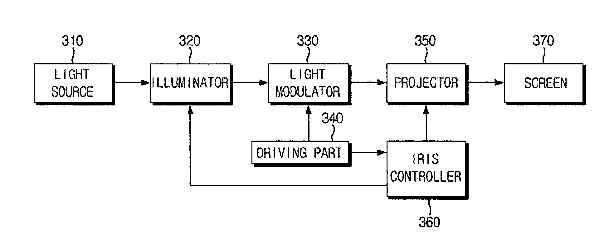
The present invention provides an optical system capable of controlling the amount of light in real time in response to changes in image reproduction. This is achieved by using a driving part to control the light modulator, a projection iris to control the amount of light projected onto the screen, and an illumination iris to control the amount of light emitted from the light source. The optical system can adjust the position of the iris to control the amount of light. The luminance information of the image is detected in real-time and used to control the amount of light emitted from the light source. This allows for real-time adjustment of the image brightness and ensures optimal viewing experience.

Problems solved by technology

The conventional optical system cannot partially increase or decrease the amount of the light since its iris has a limited opening range (area).
The increase of the C / R requires the higher C / R of the projection optical system or the DMD panel, which is limited.
Also, it is infeasible to continuously increase the C / R since the conventional iris cannot adjust the amount of light in association with the change in the image reproduction.
The conventional optical system has a disadvantage in that the amount of light is not effectively controlled since the position of the iris is restricted within the optical system.

Method used


Image

  • Optical system with iris controlled in real time
  • Optical system with iris controlled in real time
  • Optical system with iris controlled in real time

Examples


Embodiment Construction

[0041]Reference will now be made in detail to exemplary embodiments of the present invention, examples of which are illustrated in the accompanying drawing figures, wherein like reference numerals refer to like elements throughout. The embodiments are described below in order to explain the present invention by referring to the drawing figures.

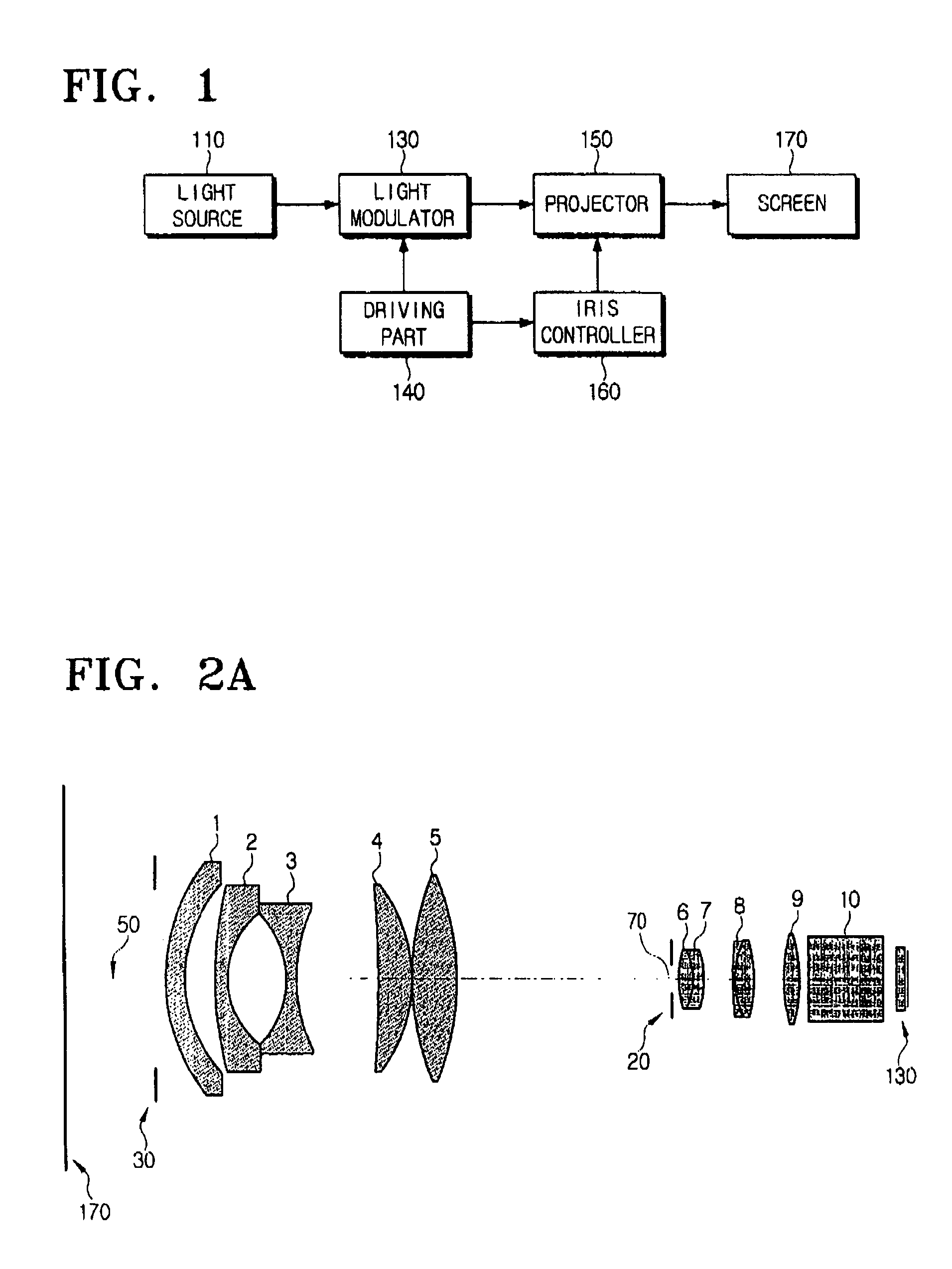
[0042]FIG. 1 is a block diagram of an optical system according to an embodiment of the present invention.

[0043]The optical system of FIG. 1 includes a light source 110, a light modulator 130, a driving part 140, a projector 150, an iris controller 160, and a screen 170.

[0044]The light source 110 may be a lamp. A light emitted from the light source 110 is condensed to the light modulator 130 via a certain lens array. The light modulator 130 modulates the light emitted from the light source 110 to a certain image. The certain image is enlarged and displayed so that a user can see the displayed image. The driving part 140 controls the light modul...


PUM

PropertyMeasurementUnit
luminanceaaaaaaaaaa
opticalaaaaaaaaaa
areaaaaaaaaaaa

Abstract

An optical system having an iris controlled in real time and a control method of amount of light thereof. The optical system includes a light source, a light modulator modulating a light emitted from the light source to a certain image, a driving part controlling the light modulator to produce the certain image and outputting luminance information of the certain image, a projector projecting the certain image, a screen on which the projected image is formed, a projection iris controlling an amount of light projected from the light modulator onto the screen, and a iris controller receiving the luminance information of the certain image from the driving part and controlling the projection iris corresponding to the luminance information of the certain image. Since the opening range of the iris is controlled in real time, the contrast ratio (C / R) is improved.

Description

CROSS-REFERENCE TO RELATED APPLICATIONS[0001]This application claims the benefit of Korean Patent Application No. 2004-16629 filed on Mar. 11, 2004 in the Korean Intellectual Property Office, the disclosure of which is incorporated herein by reference in its entirety.BACKGROUND OF THE INVENTION[0002]1. Field of The Invention[0003]The present invention generally relates to an optical system for enlarging and projecting a small-scale image onto a screen. More particularly, the present invention relates to an optical system for adjusting a contrast ratio by controlling an iris in real time.[0004]2. Description of The Related Art[0005]Complying with the demand for larger screens and higher definition of an image display device, an image projection device is rapidly prevalent which enlarges and projects a small-scale image onto a large screen using an optical system. In particular, a rear projection device, which projects an image signal from a rear side of the screen, has come into wide...

Claims


Application Information

Patent Timeline
Patent Type & Authority Patents(United States)
IPC IPC(8): G03B21/14G02F1/13357
CPCG03B21/2053G03B21/14C02F3/1247B01D21/0033B01D21/0003C02F3/121C02F2103/005
Inventor KIM, SUNG-TAENHO, JEONG-HO
Owner SAMSUNG ELECTRONICS CO LTD
Learn More