
Projection lens apparatus and rear projection type image display apparatus

a technology of projection lens and image display, which is applied in the direction of projectors, optics, instruments, etc., can solve the problems of increasing the number of aberrations generated, deteriorating assembly efficiency, and difficulty in obtaining the desired refracting power, so as to reduce costs, reduce deterioration of contrast, and improve productivity

Inactive Publication Date: 2008-07-29
HITACHI LTD
View PDF7 Cites 0 Cited by
  • Summary
  • Abstract
  • Description
  • Claims
  • Application Information

AI Technical Summary

Benefits of technology

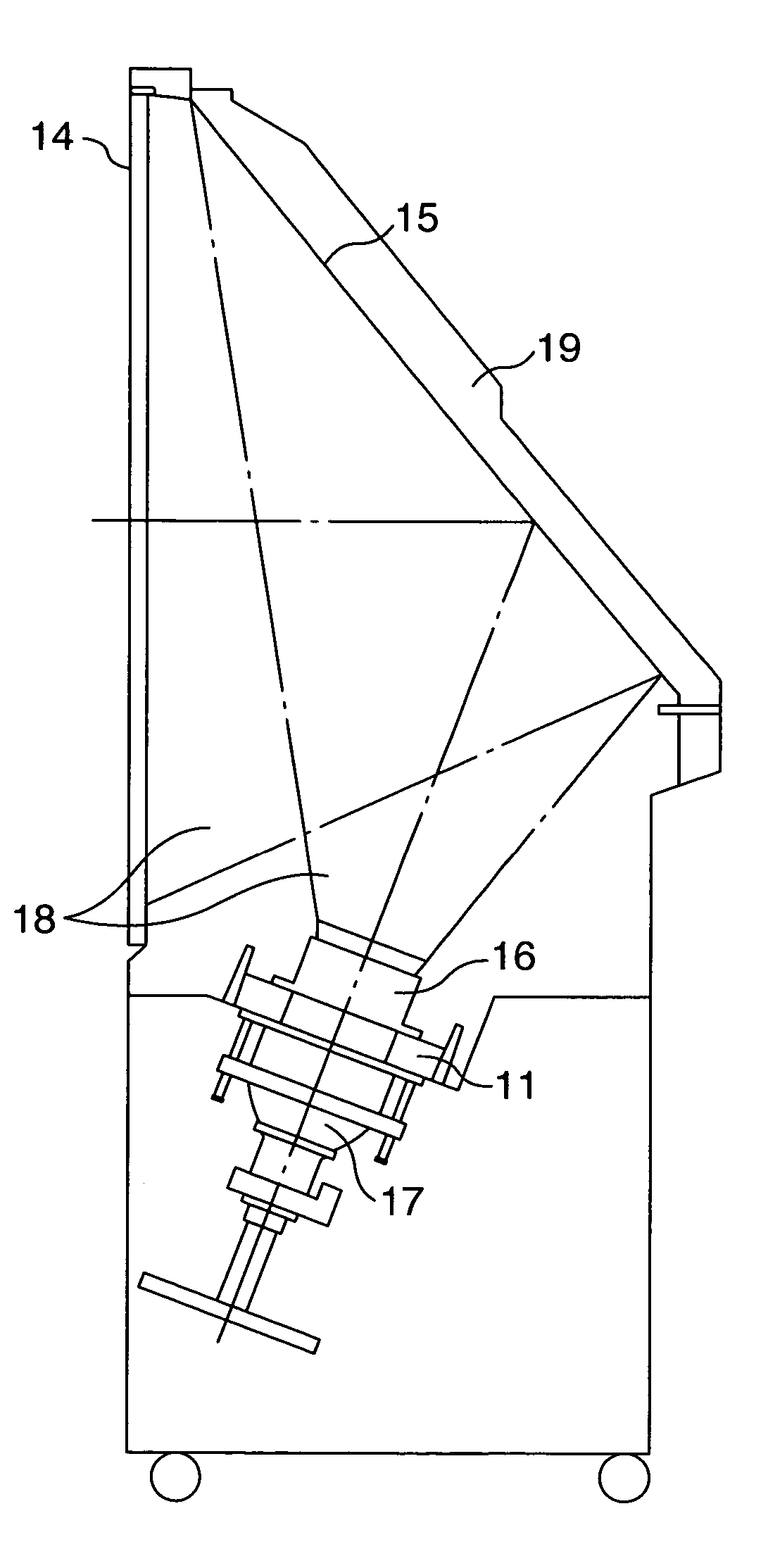
The present invention provides a technique for improving the attributes of a projection lens apparatus for a rear type image display apparatus. Specifically, the invention involves the use of a meniscus lens as an aberration correction lens that is arranged near a power lens on an image generation source side. The lens face of the meniscus lens near the screen is an aspherical surface, so that curvature is increased from a light axis of the lens face to a predetermined point located between the light axis and the outer edge, or is reduced from the predetermined point to the outer edge. This reduces physical interference between the lenses and improves assembly efficiency and productivity. Additionally, the invention addresses the issue of reducing contrast and improving the contrast of the image display apparatus.

Problems solved by technology

However, when a spherical glass lens having high dispersion and a low refractive index is employed, not only it is difficult to obtain a desired refracting power, but also the number of aberrations generated is increased.
Therefore, when lenses are assembled in a lens barrel, the power lens and the plastic lens physically interfere with each other, so that assembly efficiency is deteriorated and productivity is reduced.
Therefore, satisfactory aberration correction is difficult, and a better aberration correction capability is required.
However, further improvement of the correction capability and of contrast are difficult with the structures disclosed in JP-A-9-159914, JP-A-9-90219 and JP-A-11-344668.

Method used


Image

  • Projection lens apparatus and rear projection type image display apparatus
  • Projection lens apparatus and rear projection type image display apparatus
  • Projection lens apparatus and rear projection type image display apparatus

Examples


Embodiment Construction

[0030]The preferred embodiment of the present invention will now be described while referring to the drawings. It should be noted that the same reference numbers are provided for sections used in common for the drawings.

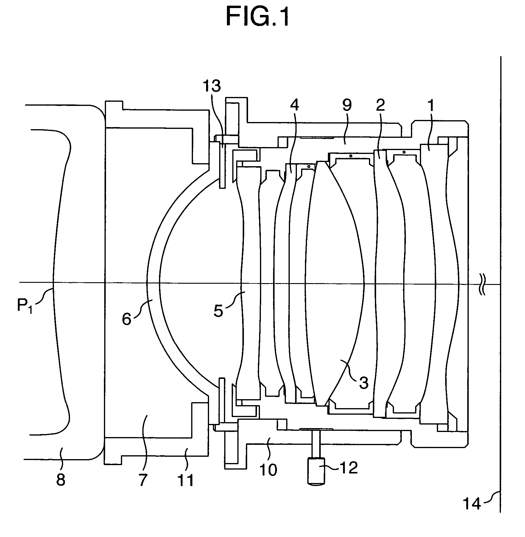
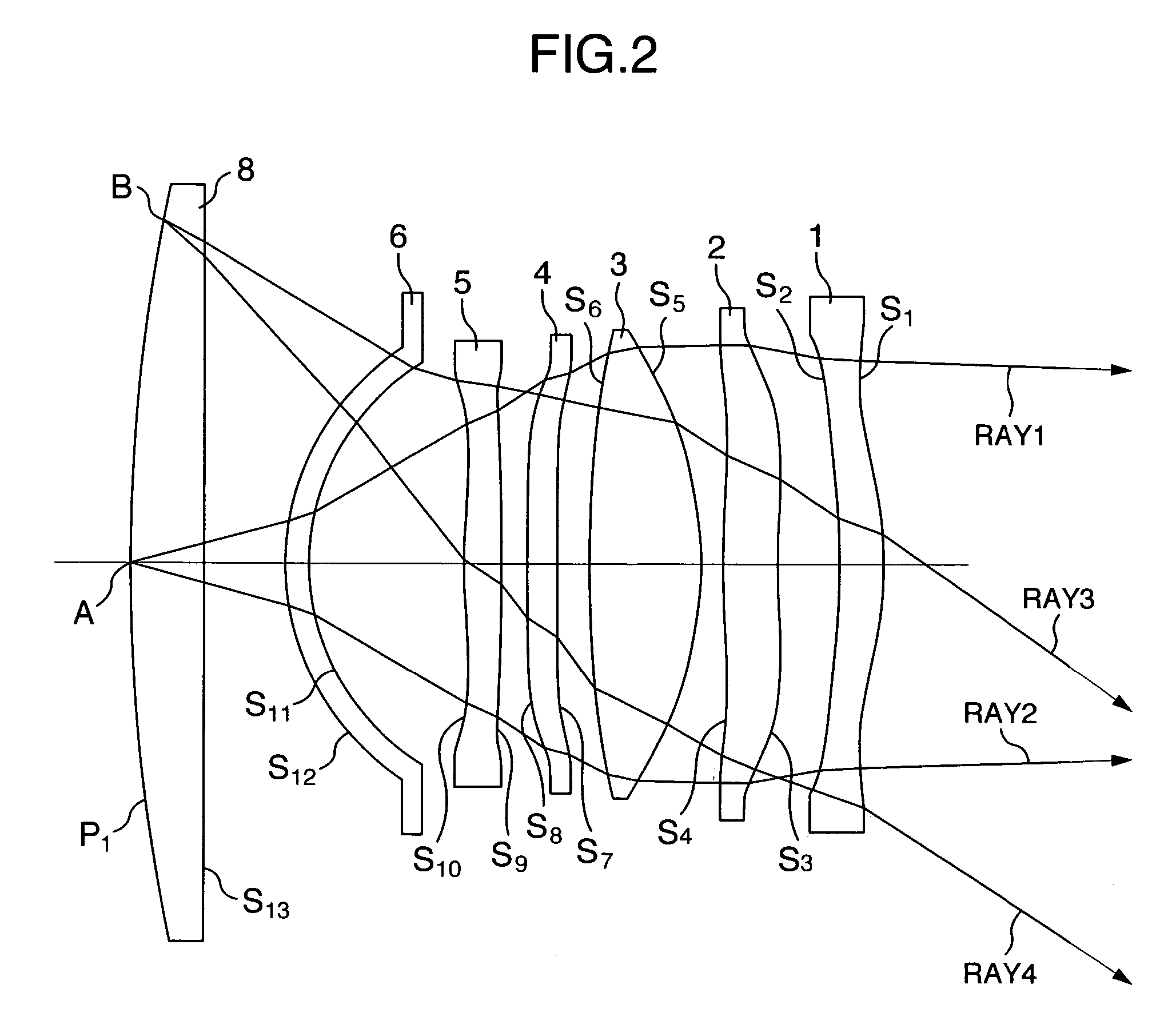
[0031]FIG. 1 is a cross-sectional view of the essential lens portion of a projection lens apparatus according to one embodiment of the invention. A first group lens 1, a second group lens 2, a third group lens 3, a fourth group lens 4 and a fifth group lens 5 are assembled in an inner lens barrel 9, and are secured to an outer lens barrel 10 by a fixing screw 12. Furthermore, the outer lens barrel 10 is fixed to a bracket 11 through a fixing plate 13 by using a screw (not shown). Then, an image on a fluorescent plane P1 of a projection tube, which is an object plane, is enlarged by the lens groups and is projected onto a rear projection screen 14. In the embodiment of the invention, the focal distance of a sixth group lens 6 is calculated that includes a projection t...


PUM


Abstract

A projection lens apparatus includes a plurality of lenses, for enlarging and projecting, onto a screen, an original image displayed on an image generation source. The plurality of lenses are arranged, beginning with the lens nearest the screen, as first to sixth lens groups. The fourth lens group includes one meniscus lens that has a positive refracting power and has a concave lens surface directed toward the screen. The concave lens surface of the meniscus lens included in the fourth group lens has a curvature in the vicinity of an outer portion of the concave lens surface that is smaller than a curvature in a predetermined area of the concave lens surface defined between a light axis of the concave lens surface of the meniscus lens and the smaller curvature of the concave lens surface in the vicinity of the outer portion of the concave lens surface.

Description

INCORPORATION BY REFERENCE[0001]The present application claims priority from Japanese application JP 2004-147125 filed on May 18, 2004, the content of which is hereby incorporated by reference into this application.BACKGROUND OF THE INVENTION[0002]1. Field of the Invention[0003]The present invention relates to a projection lens apparatus that enlarges and projects an image on a projection tube corresponding to an image generation source, and a rear projection type image display apparatus that employs this projection lens apparatus.[0004]2. Description of the Related Art[0005]A so-called six-lens structure, which employs one glass lens (hereinafter called a power lens) that has the highest refracting power and five plastic lenses having aspherical surfaces, is known as a projection lens apparatus that is employed for a rear projection type image display apparatus. A conventional projection lens apparatus using this six-lens structure is already known, as in, for example, JP-A-9-15991...

Claims


Application Information

Patent Timeline
Patent Type & Authority Patents(United States)
IPC IPC(8): G03B21/20G03B9/00G02B13/16G02B13/18G03B21/00G03B21/10G03B21/22
CPCG02B13/16G03B21/20G03B21/10G02B13/18
Inventor INADACHI, YURIKOKATO, SHUJIIKEDA, HIDEHIROOGURA, NAOYUKIHIRATA, KOJI
Owner HITACHI LTD
Learn More