
Pipelined high speed data transfer mechanism

a high-speed, data transfer technology, applied in the direction of memory adressing/allocation/relocation, multi-programming arrangements, instruments, etc., can solve the problems of processor intensive, loss of parallelism, and inability to be completely practical

Inactive Publication Date: 2008-07-15
COMMVAULT SYST INC
View PDF135 Cites 154 Cited by
  • Summary
  • Abstract
  • Description
  • Claims
  • Application Information

AI Technical Summary

Benefits of technology

The invention is a system for transferring data between two devices using a pipeline with multiple stages. It includes dedicated memory with buffers for carrying data and a master control that manages the data transfer process. The system has a first stage that allocates a buffer for collecting and processing data, and a last stage that receives and frees up a buffer for reallocation. The master control monitors the number of buffers and prevents further allocation if the current number exceeds a predetermined threshold. The technical effect of this invention is to improve the efficiency and reliability of data transfer between devices.

Problems solved by technology

This would then require copying of data between the sub-tasks, which could prove processor intensive.
The downside to this would be loss of parallelism.
A third alternative would of course be to use threads to do these tasks and use thread-signaling protocols, however, it is realized that this would not be entirely practical since threads are not fully supported on many computing platforms.

Method used


Image

  • Pipelined high speed data transfer mechanism
  • Pipelined high speed data transfer mechanism
  • Pipelined high speed data transfer mechanism

Examples


Embodiment Construction

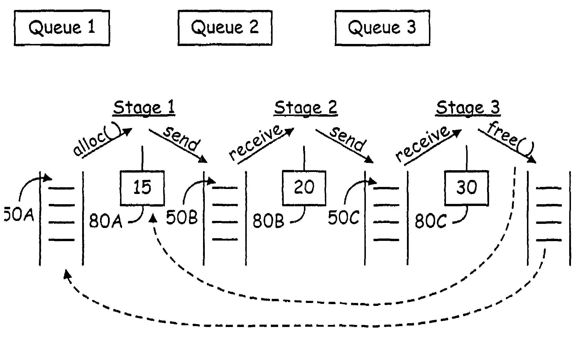
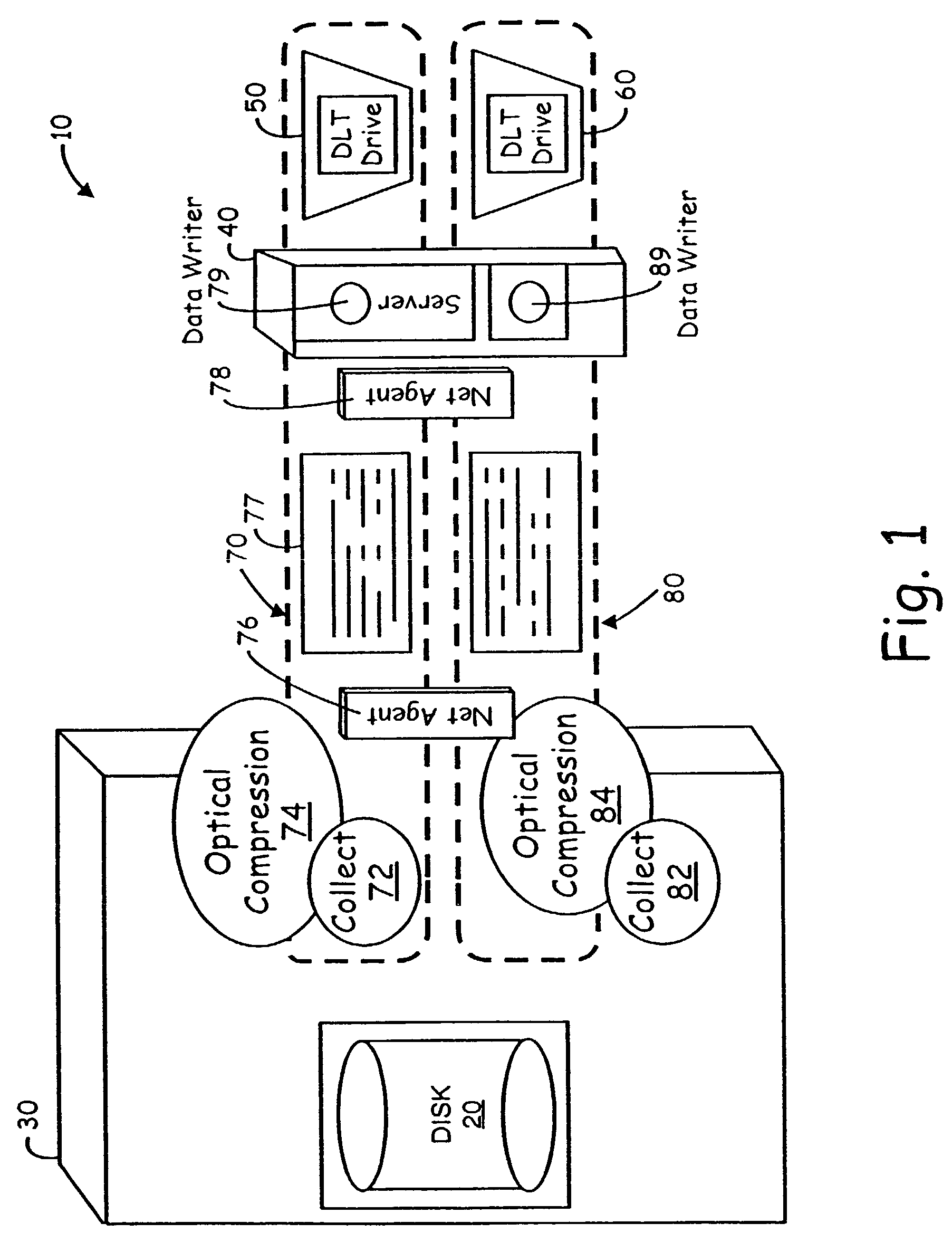
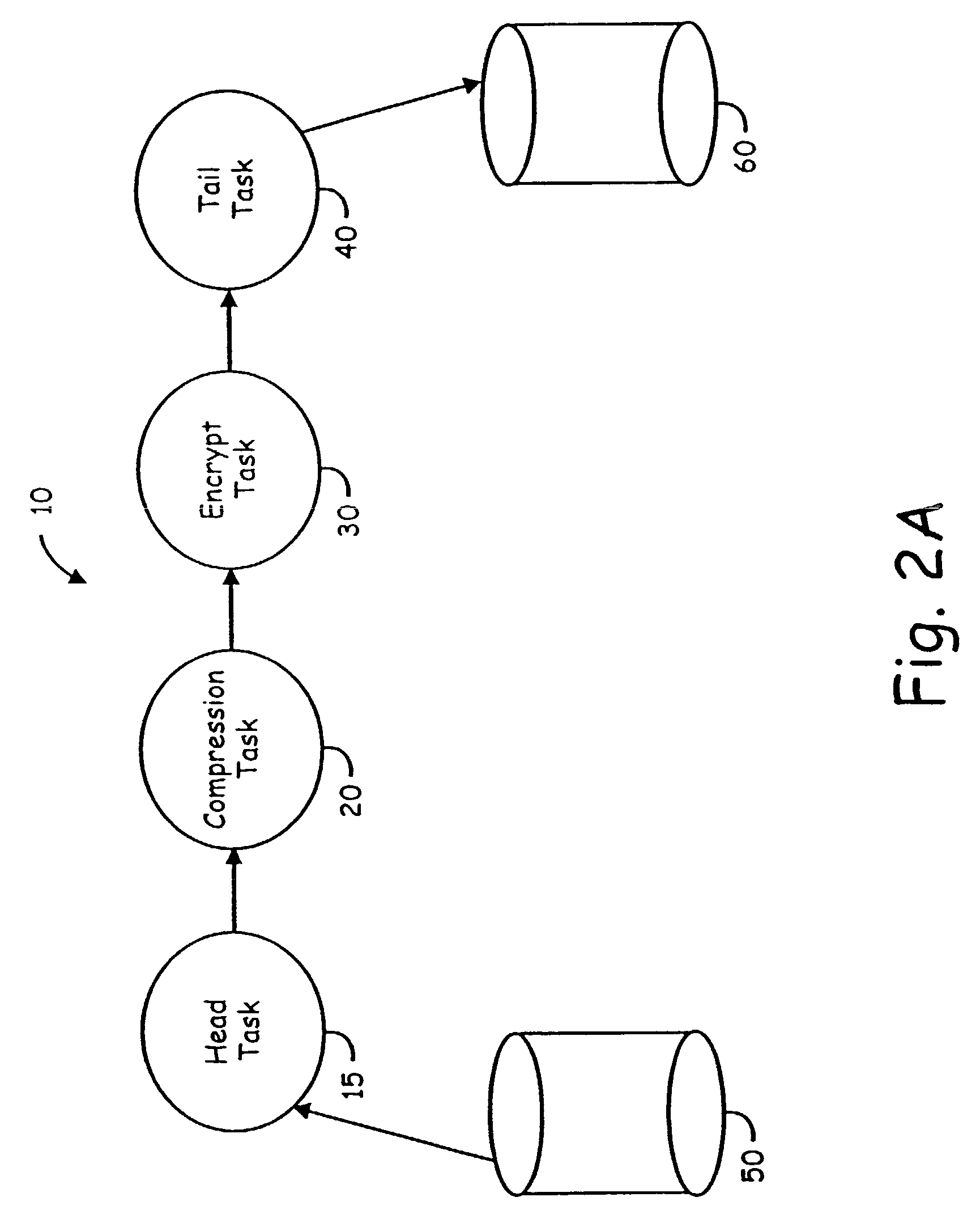
[0019]Before embarking on a detailed discussion of the data transfer mechanism of the present invention, the following should be understood. The objective of the DataPipe according to the present invention is to move data as quickly as possible from point A to point B (which may be on the same or different computers within a network) while performing a variety of operations (compression, encryption, content analysis, etc.) on the data. In order to meet this objective, parallel processing must be fully exploited, network bandwidth must be fully utilized, and CPU cycles must be minimized. The DataPipe must be efficiently implemented on a wide variety of computer systems such that heterogeneous systems on a network can use a DataPipe to transfer data to each other.

[0020]A DataPipe comprises a named set of tasks executing within one or more computers that cooperate with each other to transfer and process data in a pipelined manner. Within a DataPipe, a pipeline concept is used to improv...


PUM


Abstract

There is disclosed in a communications system having an origination storage device and a destination storage device, a data transfer pipeline apparatus for transferring data in a sequence of N stages, where N is a positive integer grater than 1, from the origination to the destination device. The data transfer apparatus comprises dedicated memory means having a predetermined number of buffers dedicated for carrying data associated with the transfer of data from the origination storage device to the destination device; and master control means for registering and controlling processes associated with the data transfer apparatus for participation in the N stage data transfer sequence. The processes include at least a first stage process for initiating the data transfer and a last Nth stage process for completing data transfer. The first stage process is operative to allocate a buffer from the predetermined number of buffers available within the dedicated memory means for collection, processing, and sending of the data from the origination device to a next stage process. The Nth stage process is operative to receive a buffer allocated to the first stage process from the (N−1)th stage process in the data transfer sequence and to free the buffer upon processing completion and storage in the destination device to permit reallocation of the buffer. The master control means further includes monitor means for monitoring the number of buffers from the pool of buffers allocated or assigned to particular processes in the pipeline, in order to prevent allocation of further buffers to a particular process when the number of buffers currently allocated exceeds a predetermined threshold.

Description

RELATED APPLICATIONS[0001]This application is a continuation of application Ser. No. 09 / 038,440, filed Mar. 11, 1998, entitled “PIPELINED HIGH SPEED DATA TRANSFER MECHANISM,” now U.S. Pat. No. 6,418,478, issued Jul. 9, 2002, which claimed priority to provisional application Ser. No 60 / 063,831 entitled “HIGH SPEED DATA TRANSFER MECHANISM” filed on Oct. 30, 1997.FIELD OF THE INVENTION[0002]The invention relates to data transfer mechanisms, and in particular, to a software-based, high speed data pipe for providing high speed and reliable data transfer between computers.BACKGROUND[0003]It is fairly obvious that data, in the process of being archived or transferred from one location to another, will pass through various phases where different operations such as compression, network transfer, storage, etc. will take place on it. There are essentially two approaches that can be taken when implementing such a transfer mechanism. One would be to split the archival process into sub-tasks, eac...

Claims


Application Information

Patent Timeline
Patent Type & Authority Patents(United States)
IPC IPC(8): G06F15/16G06F15/167G06F9/00G06F9/46
CPCG06F3/0613G06F3/0656G06F3/0685G06F9/544G06F9/5033H04L69/04G06F12/02G06F11/3495G06F11/1464
Inventor IGNATIUS, PAULPRAHLAD, ANANDTYAGARAJAN, MAHESH
Owner COMMVAULT SYST INC
Learn More