Projection image display apparatus

a projection image and display apparatus technology, applied in the field of projection image display apparatus, can solve the problems of reducing the quality of the projection image, generating brightness unevenness on the projection image, and not considering the flat light reflected between the on-light and the off-light, so as to achieve the effect of preventing brightness unevenness, high projection image brightness, and reducing the amount of ligh

Inactive Publication Date: 2008-07-08
FUJI PHOTO OPTICAL CO LTD
View PDF7 Cites 6 Cited by
  • Summary
  • Abstract
  • Description
  • Claims
  • Application Information

AI Technical Summary

Benefits of technology

[0008]It is an object of the present invention to provide a projection image display apparatus capable of preventing the brightness unevenness of the projection image due to the flat light.
[0009]Although the flat light is reflected in a direction inclined to the on-light, since the flat light is reflected toward a range having a certain angle width, a part thereof is mixed with the on-light. The intensity of the flat light is weaker as it gradually travels outward from the peak of the center of the reflective angle width. As a result, the on-light nearer to the reflective direction of the flat light among the on-light from the respective mirror elements is mixed with more flat light, and the brightness of the projection image becomes high.
[0010]Therefore, a projection image display apparatus of the present invention is equipped with a light shielding member for partially shielding the illumination light from the illuminating optical system so as to reduce the image brightness in a region where the intensity of the reflected light reflected between the on-light and off-light becomes strong, and making the intensity of the illumination light emitted to the respective mirror elements uneven.
[0012]The projection image display apparatus of the present invention makes the intensity of the illumination light emitted to the respective mirror elements uneven by using the light shielding member, and the illumination light weakened previously is emitted in the region where more flat light is mixed and the brightness of the projection image becomes high. Thereby, the brightness unevenness of the projection image can be prevented.
[0013]No unnecessary excess of the cut of the illumination light occurs by making the light shielding member a sliding type to change the emitting range of the illumination light, and the brightness unevenness can be efficiently prevented.

Problems solved by technology

On the other hand, the DMD projector has a problem in that the off-light reflected from the mirror element located at the off-position is mixed with the on-light and the quality of the projection image is reduced.
However, the related art devices absorb the off-light, and flat light reflected between the on-light and the off-light is not considered.
The flat light is reflected light from a cover glass or the like for mainly protecting the DMD, and a problem exists in that the flat light is mixed with the on-light and thereby the brightness unevenness is generated on the projection image.

Method used


Image

  • Projection image display apparatus
  • Projection image display apparatus
  • Projection image display apparatus

Examples


Embodiment Construction

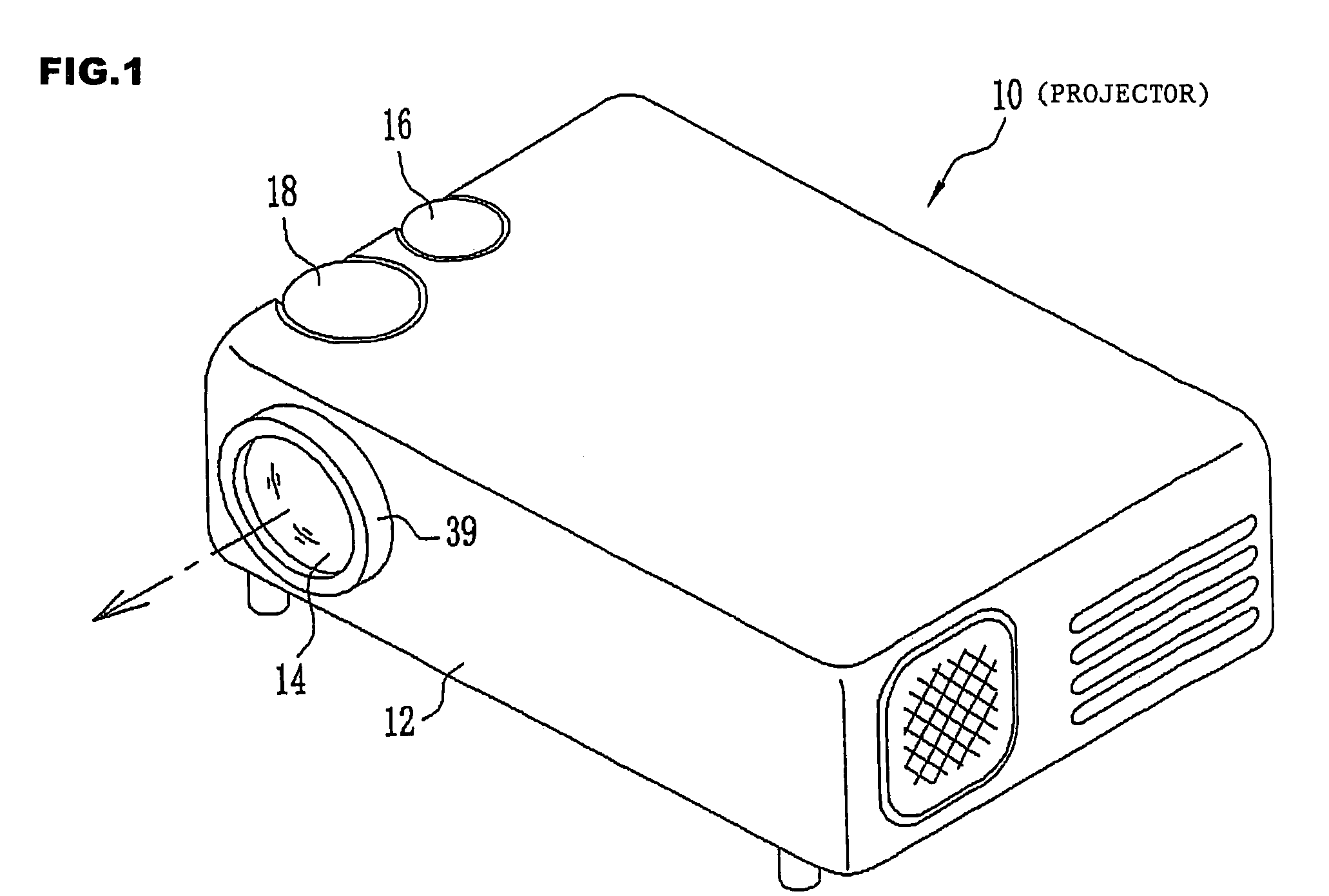
[0022]FIG. 1 shows the external appearance of a projector 10 of the present invention. A projection lens 14 is exposed on the front of a housing 12 by opening a lens cover at the time of using the projector 10. A screen 15 (see FIG. 2) is arranged in front of the projection lens 14, and an image is projected from the projection lens 14. A zoom dial 16 and a focus dial 18 are provided in the housing 12, and the variable power and focusing of the projection lens 14 can be performed by operating the dials.

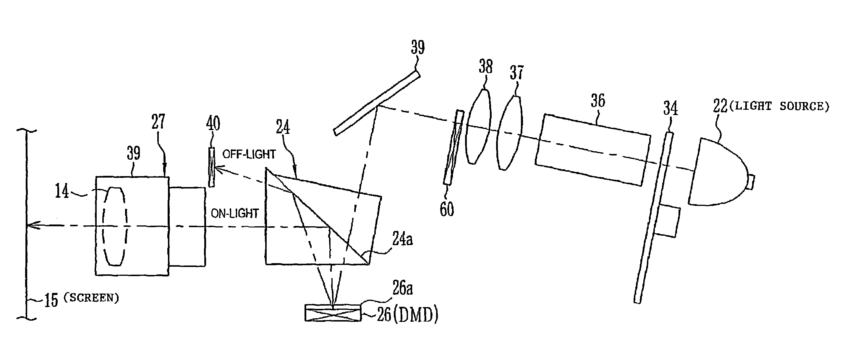
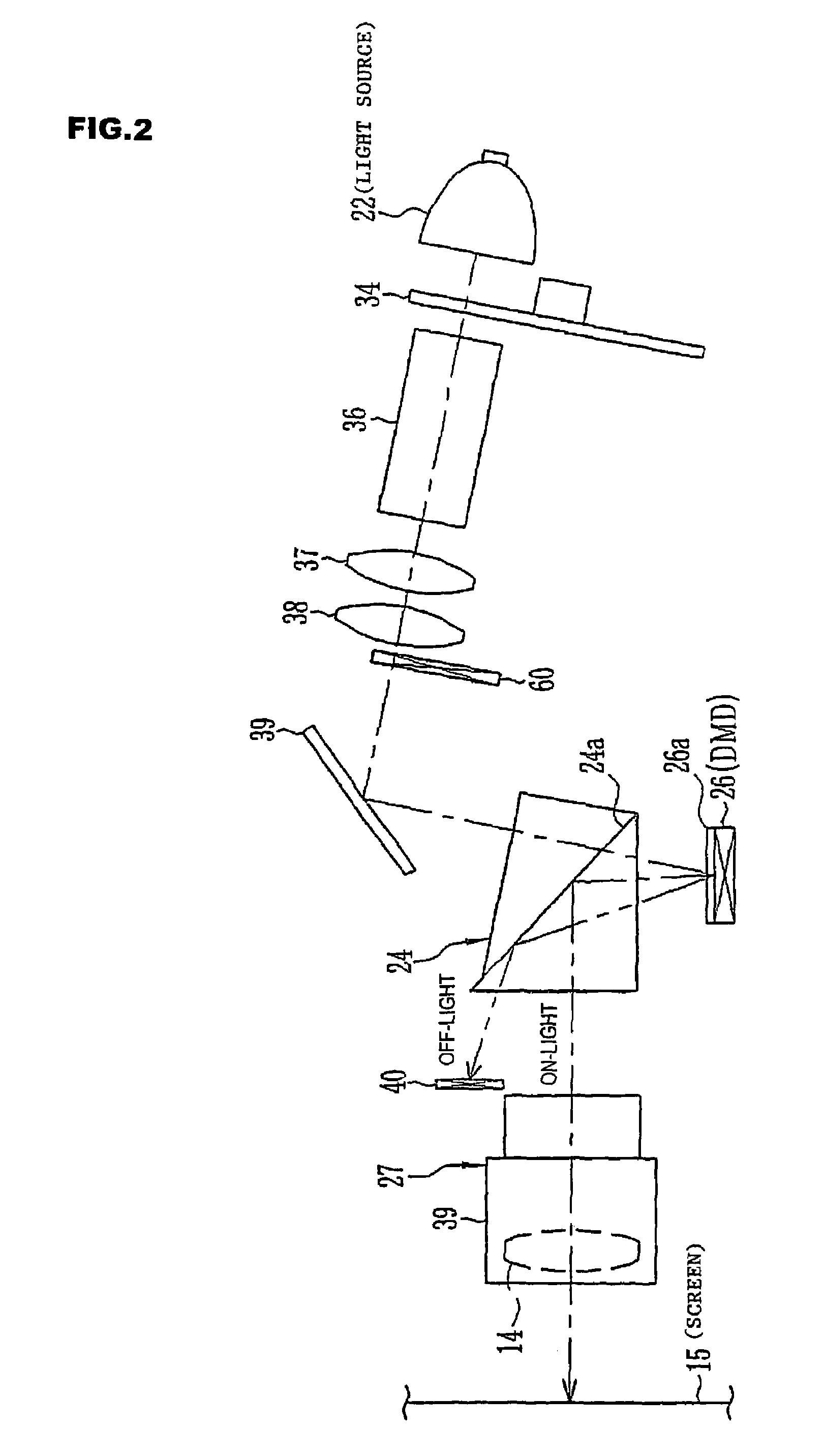
[0023]FIG. 2 shows the schematic constitution diagram of the projector 10. A light source 22, an illuminating optical system, a total reflection prism 24, a DMD 26 and a projection optical system 27 are provided in the housing 12. As the light source 22, for example, white light sources such as a xenon lamp and a mercury lamp are used. Illumination light emitted from the light source 22 enters the illuminating optical system.

[0024]The illuminating optical system is composed by a color...


PUM


Abstract

A projection image display apparatus is equipped with a light shielding member for partially shielding the illumination light from the illuminating optical system so as to reduce the image brightness in a region where the intensity of the reflected light reflected between the on-light and off-light becomes strong, and making the intensity of the illumination light emitted to the respective mirror elements uneven.

Description

[0001]This application is based on Japanese Patent application JP2004-130116, filed Apr. 26, 2004, the entire content of which is hereby incorporated by reference. This claim for priority benefit is being filed concurrently with the filing of this application.BACKGROUND OF THE INVENTION[0002]1. Technical Field of the Invention[0003]The present invention relates to a projection image display apparatus equipped with an image generation part in which a plurality of mirror elements are arranged, the mirror elements moving between an on-position at which illumination light from an illuminating optical system is reflected toward a projection optical system and an off-position at which the illumination light is reflected toward the outside of the projection optical system, whereby on-light is reflected from the mirror element located at the on-position constituting an image.[0004]2. Description of the Related Art[0005]A DMD projector provided with a DMD (digital micro mirror device) as the...

Claims


Application Information

Patent Timeline
Patent Type & Authority Patents(United States)
IPC IPC(8): G03B27/54G02B26/02G02B3/00G02B5/00G02B9/00G02B9/08G02B26/08G02B27/00G02B27/09G03B21/00
CPCG02B5/003G02B26/0833G02B27/0988G02B27/0977G02B27/0018
Inventor SHIMIZU, HITOSHI
Owner FUJI PHOTO OPTICAL CO LTD
Why Eureka
Try Eureka