
Use of E-field sensors for situation awareness/collision avoidance

a technology of situation awareness and collision avoidance, applied in the field of providing a protection zone, can solve the problem that their presence, at least for military purposes, cannot be ascertained, and achieve the effect of removing false alarms

Active Publication Date: 2008-07-08
III HLDG 1
View PDF4 Cites 39 Cited by
  • Summary
  • Abstract
  • Description
  • Claims
  • Application Information

AI Technical Summary

Benefits of technology

[0027]In terms of vehicle safety, the E-field sensors can, for instance, be used to detect an object moving relative to the vehicle which is in the protection zone of the vehicle. Thus, for instance, in a lane change situation when a vehicle in the outside lane wishes to switch to the inside lane but by doing so would cause an adjacent vehicle to be in the protection zone, the direction and the presence of the blind side vehicle can be made known to the driver and appropriate evasive action can be taken. Moreover, in terms of automatic braking when a driver is too closely following a vehicle, the presence of the vehicle in the protection zone can result in immediately alerting the driver to an impending crash or accident situation. Moreover, since the direction of the intruding object can be easily ascertained using the dual sensor approach, vehicles going in the other direction in an adjacent lane can be ignored.
[0028]A second method of discriminating against vehicles coming in the other direction is to limit the protection zone to, for instance, 5-15 feet. This has an exceedingly useful aspect of the subject invention to eliminate false alarms because the objects that can cause no harm are outside the protection zone.
[0029]E-field sensors' range can be limited by the size of the E-field sensors to eliminate, for instance, the effect of objects that would cause no harm.
[0031]This being the case, there is a simple solution to the false alarm rates associated with radars, be they lidars or microwave devices, due to limiting of the range of the E-field sensor. Secondly, the direction of the object that is within the protection zone can be readily and quickly ascertained so as to appropriately invoke whatever measures are necessary, either as a warning system or as an adaptive control system.
[0032]Finally, providing vertically mounted pairs of E-field sensors can provide elevation angle. Elevation angle can be used to discriminate against overhanging signs, trees or the like that would not interfere with the operation of a vehicle.
[0033]As will be appreciated, the provision of patches as antennas for E-field sensors is an exceptionally inexpensive way to provide a zone of protection around a vehicle, with the E-field sensors being mounted either in the bumpers or fenders of the vehicle or within the doors or other exterior vehicle surfaces. Because the sensors themselves are planar, or can be made to conform to any surface, they are visually undetectable so that they can be readily incorporated into vehicles without altering the appearance of the vehicle. This is useful for consumer-oriented items such as automobiles, but is also useful in the military context so as not to alert an intruder or enemy combatant as to the existence of such a protection system. Moreover, since these systems are completely passive, other individuals or enemy troops are not apprised of the existence of the protection system around the vehicle. Having visible protection permits enemy troops to avoid such vehicles and attack those who do not have protection.

Problems solved by technology

Therefore their presence, at least for military purposes, cannot be ascertained.

Method used


Image

  • Use of E-field sensors for situation awareness/collision avoidance
  • Use of E-field sensors for situation awareness/collision avoidance
  • Use of E-field sensors for situation awareness/collision avoidance

Examples


Embodiment Construction

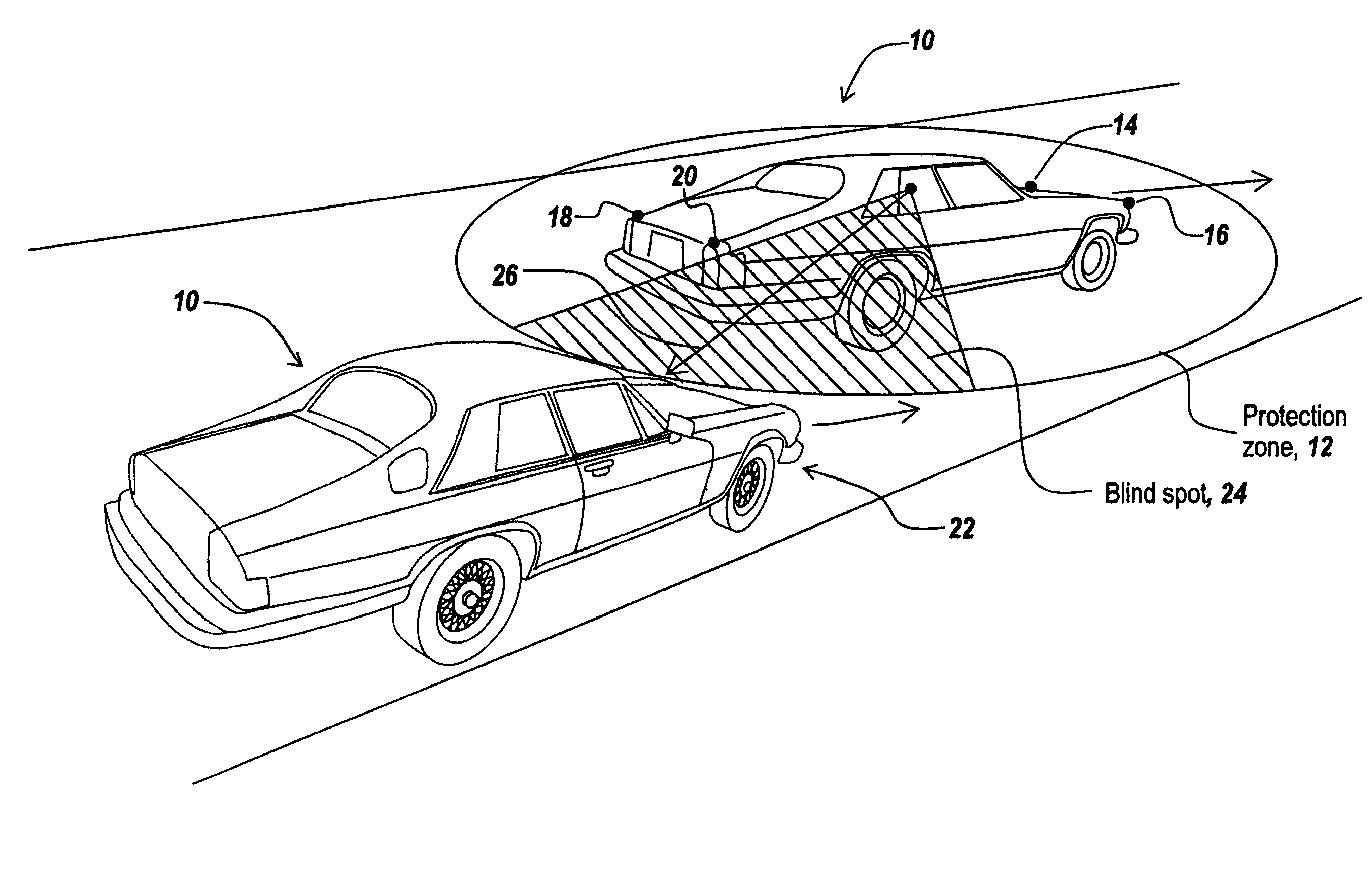
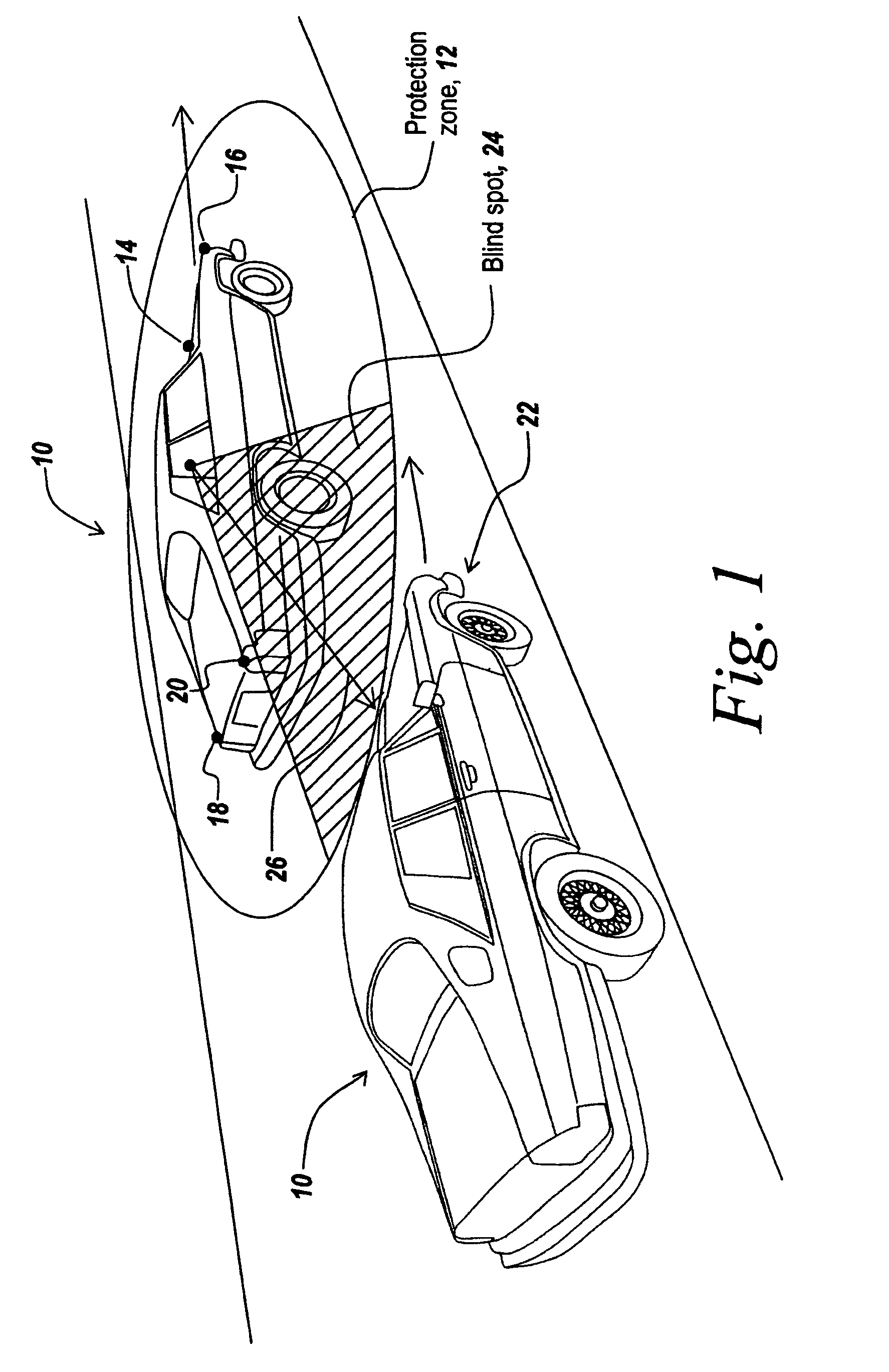
[0045]Referring now to FIG. 1, a vehicle 10 has a system that establishes a protection zone 12 about the vehicle through the use of pairs of E-field sensors, here illustrated at 14, 16, 18 and 20 respectively located on the front and rear bumpers of the vehicle.

[0046]As is common during a lane change operation when, for instance, a vehicle in an outer lane wants to proceed to an inner lane, if there is a vehicle 22 in a blind spot 24 in the rear quarter of the viewing of the driver of the vehicle, it is important to be able to alert the driver that there is an impediment to the lane change, meaning that there is a vehicle into which he or she would run if the lane change were executed.

[0047]As will be described hereinafter, pairs of E-field sensors can be located on a vehicle to establish protection zone 12, which in one embodiment extends approximately 15 feet around the vehicle.

[0048]The relative motion of vehicle 22 with respect to vehicle 10 is sensed by the E-field sensors and ...


PUM


Abstract

E-field sensors are used to establish a protection zone around a vehicle so as to detect the presence of objects within the protection zone, be they other vehicles or individuals. In one embodiment the direction to the intruding object is established by virtue of the use of pairs of E-field sensors. In a further embodiment the range of the E-field sensors determines the limited protection zone around the vehicle. Because of the limited protection zone, false alarms are greatly reduced.

Description

REFERENCE TO RELATED APPLICATIONS[0001]This application claims rights under 35 USC § 119(e) from U.S. patent application Ser. No. 11 / 148,499 filed Jun. 9, 2005 by Paul A. Zank et al. entitled “Method and Apparatus for Detecting Individuals Using Electrical Field Sensors,” assigned to the assignee hereof and incorporated herein by reference; U.S. patent application Ser. No. 11 / 104,125 filed Apr. 12, 2005 by Eugene S. Rubin et al. entitled “Method and Apparatus For Avoidance Of Power Lines or Trip Wires By Fixed and Rotary Winged Aircraft,” assigned to the assignee hereof and incorporated herein by reference.FIELD OF THE INVENTION[0002]This invention relates to providing a protection zone around a vehicle and more particularly to the use of electrical field (E-field) sensors to detect the presence and location of other vehicles and / or individuals within the protection zone.BACKGROUND OF THE INVENTION[0003]As has recently been described, there is a growing market for adaptive cruise co...

Claims


Application Information

Patent Timeline
Patent Type & Authority Patents(United States)
IPC IPC(8): B60Q1/00
CPCB60Q9/008G01V3/088B66F17/00
Inventor RUBIN, EUGENE S.ZANK, PAUL A.ZEMANY, PAUL D.SUTPHIN, ELDON M.
Owner III HLDG 1
Learn More