
Balanced filter device

a filter device and filter technology, applied in coupling devices, electrical devices, waveguides, etc., can solve the problems of difficult to ensure the band characteristic required for the filter, the reduction of the size is difficult to realize, and the inability to ensure the flexibility of design in a limited space, etc., to achieve the effect of small structure and high attenuation

Active Publication Date: 2008-07-08
TAIYO YUDEN KK
View PDF17 Cites 44 Cited by
  • Summary
  • Abstract
  • Description
  • Claims
  • Application Information

AI Technical Summary

Benefits of technology

[0016]Accordingly, it is an object of the present invention to provide a balanced filter which is effective in realizing a high attenuation and a size reduction.

Problems solved by technology

Accordingly, the disclosed structures are usable as a balun, but they have a difficulty in ensuring a band characteristic required for the filter.
However, the structure in which a balun section and a filter section are separately formed and integrated together has the problem as follows.
Therefore, satisfactory flexibility in design cannot be ensured in a limited space, and a reduction of the size is very difficult to realize.

Method used


Image

  • Balanced filter device
  • Balanced filter device
  • Balanced filter device

Examples


Embodiment Construction

[0128]Embodiments of the present invention will be described in detail below with reference to the accompanying drawings. Note that the present invention is not limited to the following embodiments and can be modified as required.

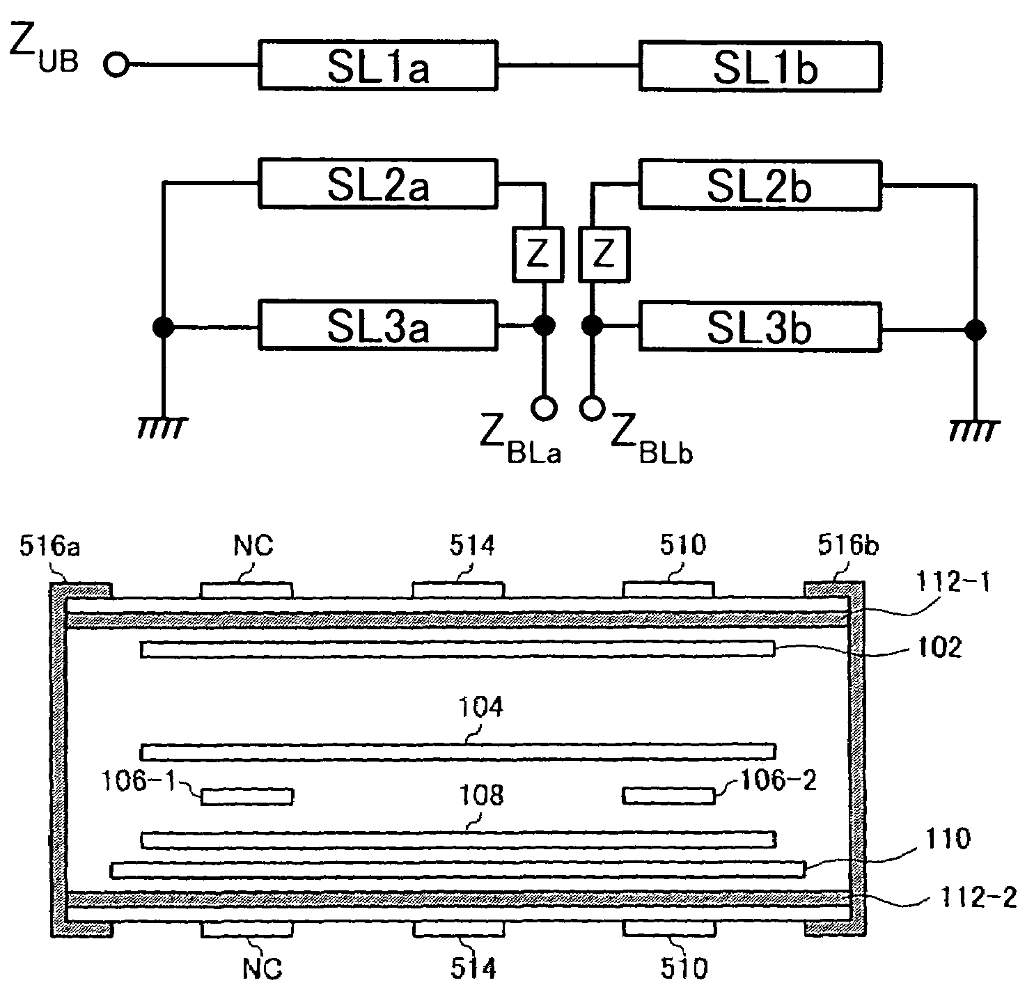
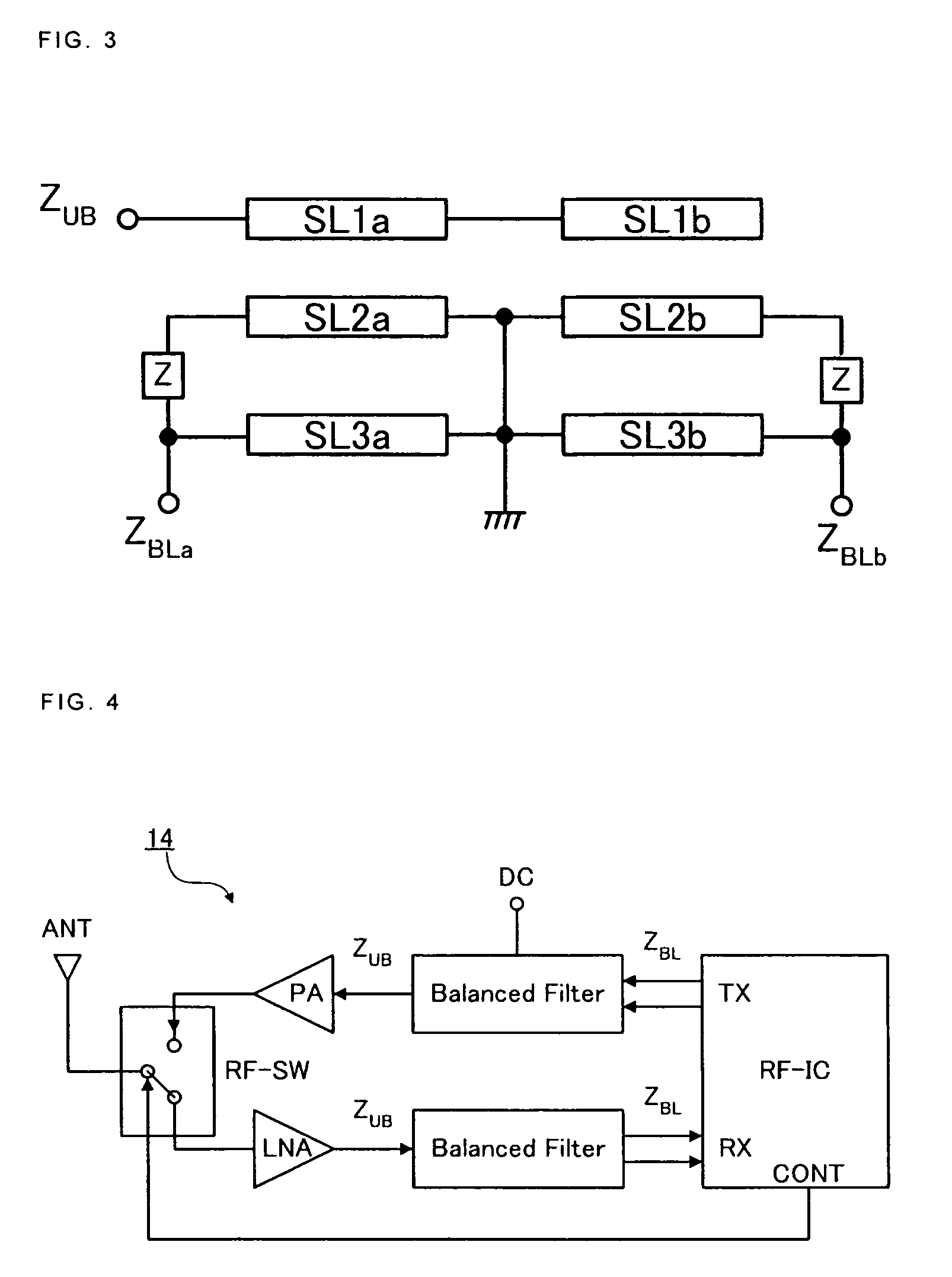
[0129]FIG. 1 is an equivalent circuit diagram showing features of a balanced filter according to one embodiment. As shown in FIG. 1, the balanced filter according to this embodiment comprises strip-line resonators SL1a and SL1b constituting resonance electrodes on the unbalanced side, strip-line resonators SL2a and SL2b constituting resonance electrodes on the balanced side, strip-line resonator SL3a and SL3b constituting stage constituting resonance electrodes, and impedance elements Z coupling the resonance electrodes on the balanced side to the stage constituting resonance electrodes.

[0130]The unbalanced-side resonance electrodes SL1a and SL1b are each formed of a λ / 4 strip-line. As shown in FIG. 1, those strip-lines are connected to each other at their ...


PUM


Abstract

A balanced filter suitable for a reduction of the filter size. The balanced filter comprises strip-line resonators (SL1a, SL1b) constituting resonance electrodes on the unbalanced side, strip-line resonators (SL2a, SL2b) disposed in adjacently opposed relation to the strip-lines on the unbalanced side and constituting resonance electrodes on the balanced side, strip-line resonators (SL3a, SL3b) disposed in adjacently opposed relation to the strip-lines on the balanced side and constituting stage constituting resonance electrodes, and impedance elements (Z) coupling the resonance electrodes on the balanced side to the stage constituting resonance electrodes.

Description

BACKGROUND OF THE INVENTION[0001]1. Field of the Invention[0002]The present invention relates to a balanced filter having the function of a balun performing conversion between unbalanced and balanced signals and the function of a filter performing band control, and more particularly to a balanced filter effective in reducing a filter size.[0003]2. Description of the Related Art[0004]Radio communication equipment comprises various RF (radio frequency) devices, such as an antenna, a filter, an RF switch, a power amplifier, an RF-IC, and a balun. Among these parts, resonance devices, such as an antenna and a filter, handle an unbalanced signal on the basis of the ground potential, while an RF-IC for producing and processing an RF signal handles a balanced signal. A balun functioning as an unbalance-balance transformer is therefore used when those two types of parts are connected to each other.[0005]That type of balun is disclosed, for example, in the following Patent Documents:[0006]Pa...

Claims


Application Information

Patent Timeline
Patent Type & Authority Patents(United States)
IPC IPC(8): H01P1/203
CPCH01P5/10H01P1/20381
Inventor YASUDA, HISAHIROKOSAKA, TAKESHIINOUE, MAKOTO
Owner TAIYO YUDEN KK
Learn More