
Method for manufacturing high density pile fabrics

a technology of woven piles and fabrics, applied in the direction of weaving, woven fabrics, textiles and paper, etc., can solve the problems of difficult to apply to the design, difficult to distinguish fabric patterns, and difficult to form delicate designs, and achieve the effect of high density and nice back

Inactive Publication Date: 2008-07-08
VAN DE WEILE N V MICHAEL
View PDF26 Cites 18 Cited by
  • Summary
  • Abstract
  • Description
  • Claims
  • Application Information

AI Technical Summary

Benefits of technology

[0032]The expert skilled in the art knows that mixed contours may be avoided when weaving pile fabrics by inserting only one weft into the fabric at each weft insertion cycle. This method is known for use on a face-to-face weaving machine having only one weft insertion means (single gripper weaving machine).
[0037]By this method it is possible to manufacture high density pile fabrics without mixed contours occurring.
[0039]In a preferred method according to the invention, the non pile forming pile warp yarns to be interlaced in the upper fabric and the non pile forming pile warp yarns to be interlaced in the lower fabric will maintain their positions with respect to the weft insertion means during the non pile formation. This has the great advantage that the non pile forming pile warp yarns which are interlaced in the upper fabric, will maintain their positions between the upper and the central weft insertion means and that the non pile forming pile warp yarns which are interlaced in the lower fabric will maintain their positions between the central and the lower weft insertion means. In this manner, only the pile forming pile warp yarns will have to be moved out of or through the bundle of pile warp yarns. This manner very strongly favours the forming of the shed at higher densities of pile warp yarns and will finally lead to a lower consumption of pile warp yarns.
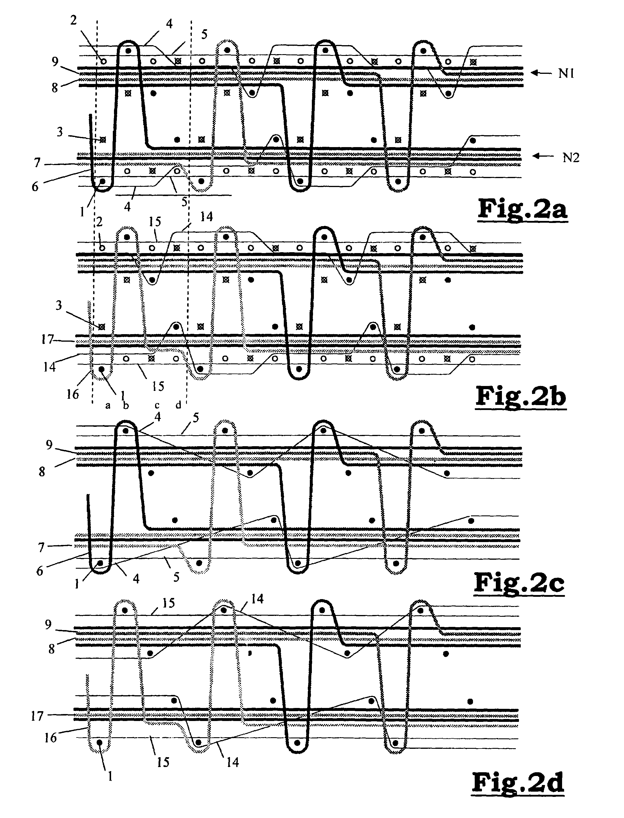
[0048]If a same pile warp yarn is interlaced around the four successive wefts of a series, pile tufts of different adjacent pile burls will indeed be found without being separated by a weft yarn, but this wefts are not crossing in the face-to-face fabric, so that there will be no mixed contour. The two pile tufts of the same colour are standing nicely upright next to one another and they will also maintain this position in the fabric. This means that the pile density of the fabric in part of the fabric or almost the entire fabric may be increased without mixed contours occurring and with preservation of a delicate design and a nice back of the fabric.
[0049]In a more particular method according to the invention, the tension warp yarns of the upper and lower fabric are positioned outside the upper and lower weft insertion means respectively, each time no weft yarn is inserted at the back of the respective fabric and the tension warp yarns of the upper and lower fabric are positioned between the upper and the lower weft insertion means respectively and the central weft insertion means being positioned, each time a weft yarn is inserted at the back of the respective fabric. This has, among others, the advantage that the tension warp yarn in the lower fabric is used as a support for the lower weft insertion means when it is moving through the shed without a weft yarn.
[0050]High densities of warp yarns in the weft direction are realized by a combination of a large number of warp yarn systems per metre and a large number of chores. The large number of warp systems per metre is obtained, by providing at least two pile warp systems per reed dent, in a particularly advantageous embodiment of the method according to the invention. This has the great advantage that by using this method, fabrics having a high density, more particularly of more than 40 pile warp yarns per centimetre, may be manufactured, without mixed contours occurring.

Problems solved by technology

Only, when weaving the 1 / 2 V texture by means of the multiple rapier technique, the problem may occur that mixed contours are produced, preventing delicate designs from being formed, which is rather inconvenient in fabrics of this density.
Because the two pile tufts are crossing with this colour change, they will take up a wrong position with respect to one another in accordance with what is desired and this will cause the pattern of the fabric to become indistinct.
In the very delicate patterns to be woven by means of the devices as described above, applying these applications to the design is very labour intensive.
Moreover, the liberty of designing in delicate drawings will be restricted.
Moreover the delicate designing requires (typical of fabrics imitating hand-knotted carpets) a freedom of designing, which is not always to be realized by avoiding mixed contours as described above.
The 1 / 1V method and the 1 / 2V method as described before, moreover, have the disadvantage that they are restricted to about 40 pile warp yarns per centimetre with double rapier weaving machines which are normally used.
At higher densities of pile warp yarns, there will be problems as to the perfectness of the quality of the back and the dead pile protruding from the back of the fabric.
With polypropylene yarns also, which are smoother, these problems will occur, but in that case rather from 42 to 45 pile warp yarns per centimetre.
This means, that a fabric having a high density and many colours will cause problems to be woven, both with a 1 / 1V and 1 / 2V weave, on a double rapier weaving machine in the following structures:600 pile warp systems per metre in 7 chore and more:700 pile warp systems per metre in 6 chore and more:800 pile warp systems per metre in 5 chore and more.

Method used


Image

  • Method for manufacturing high density pile fabrics
  • Method for manufacturing high density pile fabrics
  • Method for manufacturing high density pile fabrics

Examples


Embodiment Construction

[0062]The face-to-face pile fabric represented in the figures consists of an upper an a lower backing fabric. Both backing fabrics consist of binding warp yarns, tension warp yarns and weft yarns. Pile forming pile warp yarns are alternately interlaced in the upper and the lower fabric around a weft yarn, whereas non pile forming (dead) pile warp yarns are interlaced in the upper or the lower backing fabric and each of which is positioned on a different level (N1, N2).

[0063]Each figure is made up of four parts (a), (b), (c) and (d), where (a) is representing the course of the pile warp yarns (6, 7, 8, 9) of one pile warp system within one reed dent with the accessory part of the backing warp yarns (4, 5) and (b), the pile warp yarns (16, 17, 18, 19) of another pile warp system within the same reed dent with its accessory backing warp yarns (14, 15). Both in (a) and in (b) the positions of the weft insertion means are indicated with respect to the warp yarns and is indicated with whi...


PUM


Abstract

The present invention relates to a method for face-to-face weaving of a pile fabric on a weaving machine, pile forming pile warp yarns (6, 7, 8, 9, 16, 17, 18, 19) being interlaced alternately around a weft yarn (1) in the upper fabric and around a weft yarn (1) in the lower fabric and non pile forming pile warp yarns (6, 7, 8, 9, 16, 17, 18, 19) being interlaced in one of the backing fabrics in accordance with a predetermined pattern, the said weaving machine comprising at least three weft insertion means and that at each weft insertion cycle only one weft yarn is inserted, the non pile forming pile warp yarns (6, 7, 8, 9, 16, 17, 18, 19) to be interlaced are positioned on a different level (N1, N2) and, in successive series of four weft insertion cycles (a, b, c, d) each time during two successive weft insertion cycles one weft yarn (1) being inserted (a, b) under the two levels (N1, N2) and one weft yarn (1) being inserted above the two levels (N1, N2) and each time, during two other successive weft insertion cycles (c, d) one weft yarn (1) being inserted in each of these weft insertion cycles between the said levels (N1, N2).

Description

[0001]This application claims the benefit of Belgian Application No. 2005 / 0591 filed Dec. 6, 2005, which is hereby incorporated by reference in its entirety.BACKGROUND OF THE INVENTION[0002]The present invention relates to a method for manufacturing face-to-face woven pile fabrics, two backing fabrics being woven above one another on a weaving machine by inserting weft yarns in successive weft insertion cycles between binding and tension warp yarns, the pile warp yarns forming a pile in at least one part of the pile fabric by being alternately interlaced around a weft yarn in the upper backing fabric and around a weft yarn in the lower backing fabric and pile warp yarns forming no pile in at least another part of the pile fabric and being interlaced in one of the backing fabrics in accordance with a predetermined pattern. More particularly, the present invention is relating to a high density pile fabric manufactured in accordance with the present method.[0003]Furthermore, the presen...

Claims


Application Information

Patent Timeline
Patent Type & Authority Patents(United States)
IPC IPC(8): D03D39/16D03D39/18D03D47/12D03D39/10D03D47/27
CPCD03D39/16D03D27/10
Inventor DEBAES, JOHNY
Owner VAN DE WEILE N V MICHAEL
Learn More