
Instrument and method for delivery of anaesthetic drugs

a technology of anaesthesia and instruments, applied in the field of medical surgical instruments, can solve the problems of nerve damage in manipulating the needle tip, the uncertainty of the position of the needle tip, and the reference methods and apparatus available to accomplish such methods, so as to prevent the needle from doing any damage to the tissues of the patient, and easily vary the current

Inactive Publication Date: 2008-06-10
TELEFLEX LIFE SCI LTD
View PDF40 Cites 35 Cited by
  • Summary
  • Abstract
  • Description
  • Claims
  • Application Information

AI Technical Summary

Benefits of technology

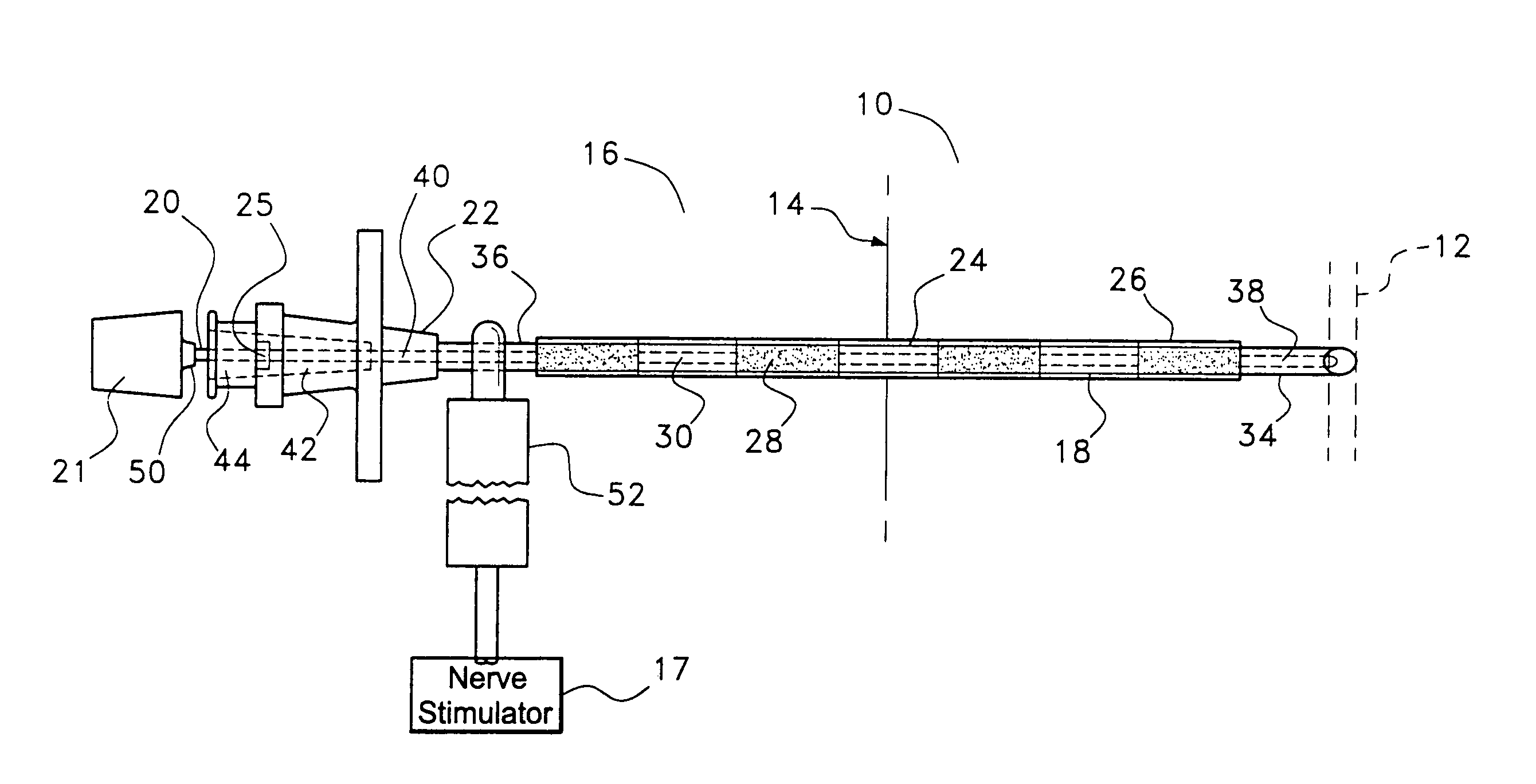
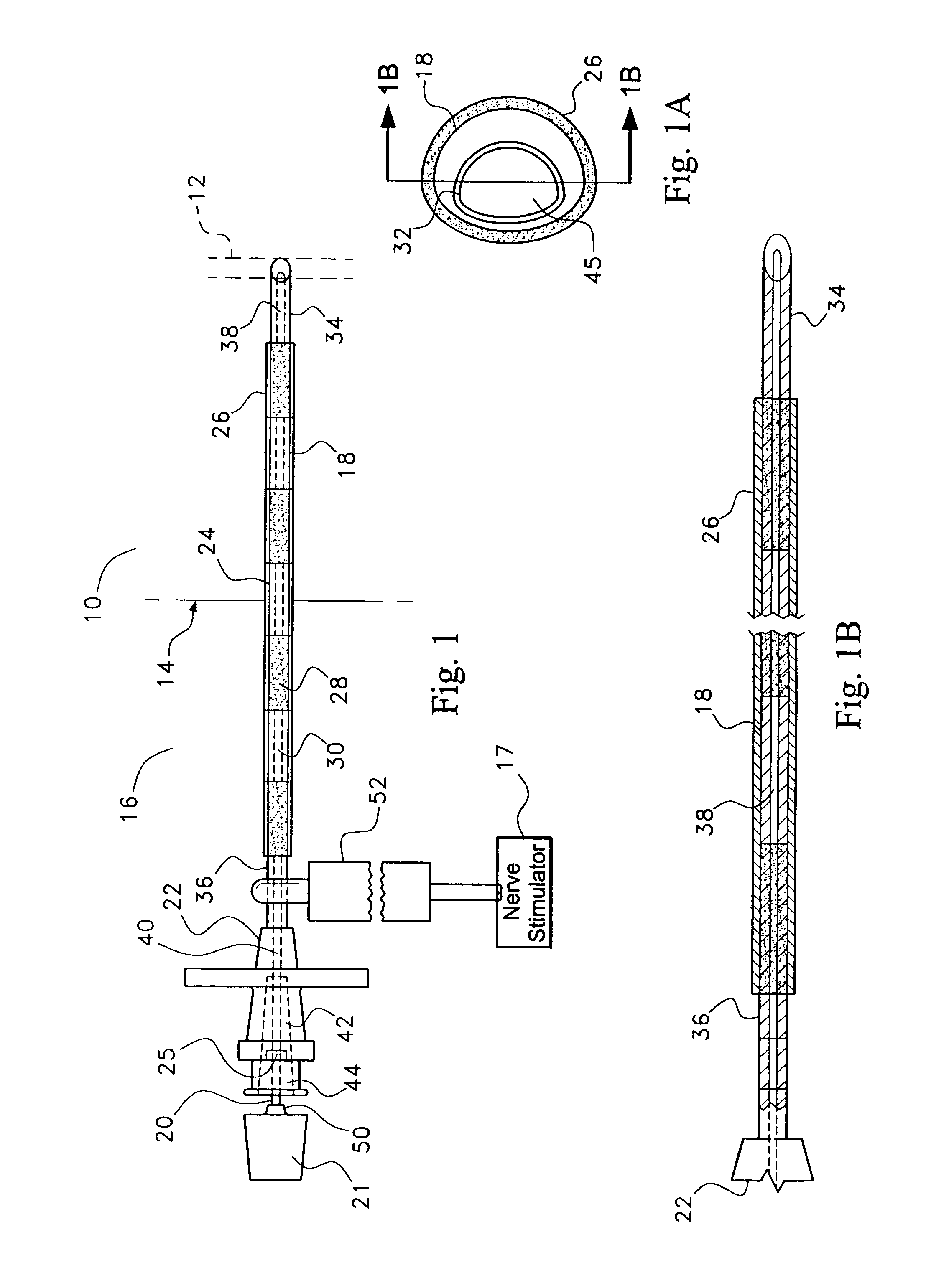
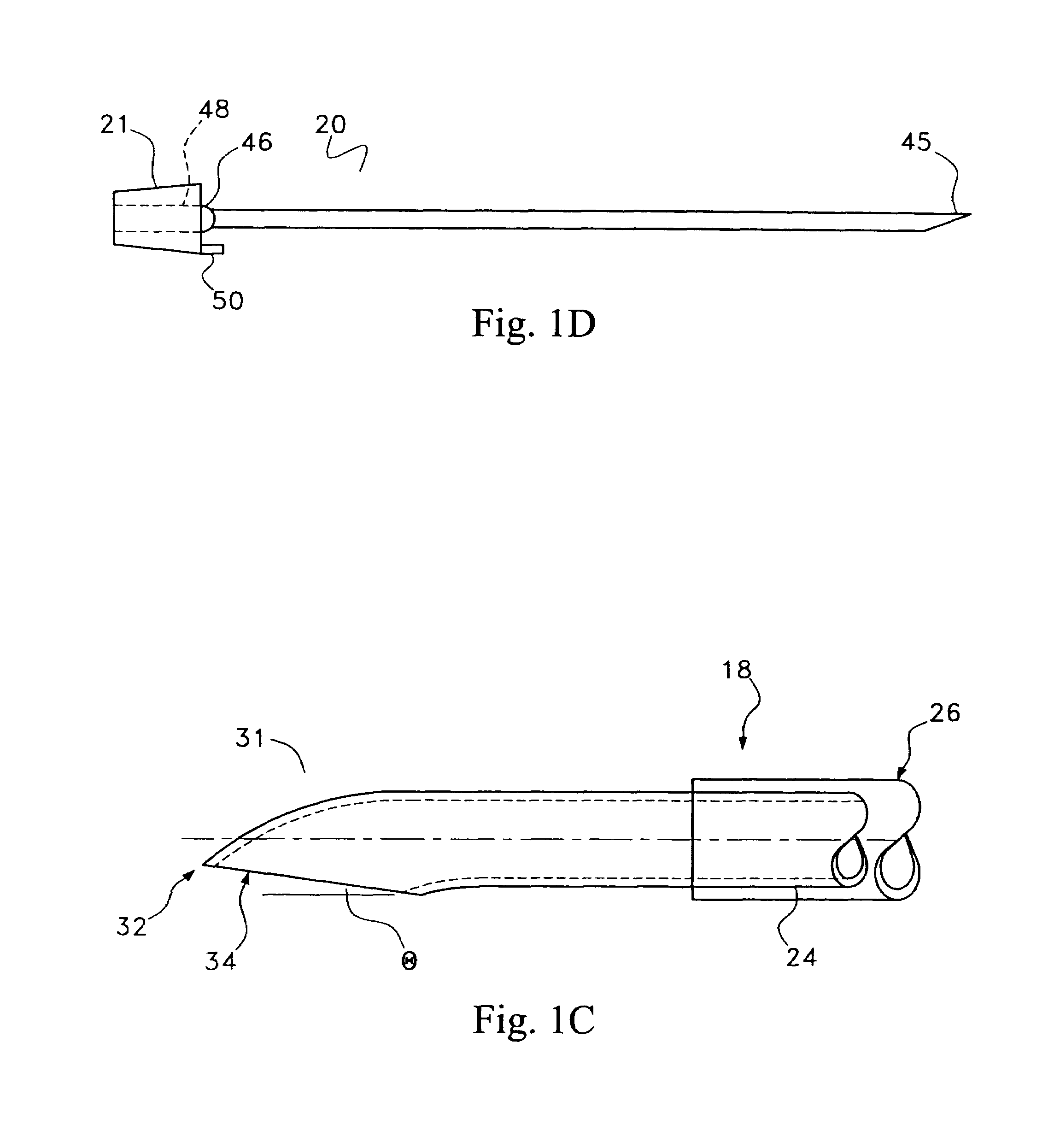
[0008]The needle has a distal end and a proximal end. The distal end of the needle terminates in a beveled aperture having a sharp tip adapted for insertion into a nerve sheath of a patient so as to abut the nerve plexus. Contained in the needle and co-terminus therewith at the distal end is a removable stylet utilized in easing insertion of the needle into the patient. The proximal end of the needle is provided with a hub portion used for gripping the needle as well as for accessing the central bore of the needle. The needle, being of metal construction, is electrically conductive along its entire length. A non-conductive material may be used to coat the outer surface of the needle, leaving exposed at least the distal tip of the needle, such that electrical voltage is not expended in unnecessary places.
[0009]A control device may be associated with the stimulating needle. The control device allows the operator to exercise control over the electrical stimulating pulse being applied to the nerve of the patient without removing either hand from the stimulating needle. Associating the control device directly with the stimulating needle has many advantages, including allowing the person inserting the needle to concentrate all of his attention on the patient and the stimulating needle without the need to operate or direct the operation of a separate, i.e. remote, stimulating control apparatus. In addition, a display may also be associated with the stimulating catheter. Such a readout would provide the operator with information as to the electrical impulse being applied to the patient's nerve. Again, the ability to focus on the single needle structure instead of referencing an independent readout remote from the stimulating needle allows for effective and safe operation of the stimulating needle and / or the stimulating catheter.
[0010]The stimulating catheter is adapted for insertion through the hub portion and within and through the needle, with the distal end of the catheter capable of protruding out of the needle's distal end. The catheter is formed primarily of a thermoplastic or related material which may be supported by a tightly wound helical wire. The helical wire can extend beyond the sheath material of the catheter at either or both the proximal and distal ends of the sheath. The sheath either alone or in combination with the helix formed by the helical wire, leaves the center of the catheter structure available as a conduit. This central conduit or lumen of the catheter allows for administration of anaesthetic to the proximal end of the catheter. The wire coil may be covered with an insulating material other than the thermoplastic cover. This insulating material, e.g. TEFLON, may surround the entire circumference of the wire as it is formed, prior to being coiled. Alternatively, this insulating material may be applied to the wire after it has been formed into a helical shape. In either case, the insulating material is typically much thinner than the thermoplastic cover applied after coiling of the wire.
[0011]The proximal end of the catheter may be inserted into a multipurpose connector. Once the proximal end of the catheter is inserted into the retaining portion of the multipurpose connector, the multipurpose connector may be manipulated to rigidly capture the proximal end of the catheter. The structure of the multipurpose connector allows the proximal end of the catheter to be accessed by a syringe or other apparatus for injecting fluid through the catheter. The multipurpose connector is also provided with electrical connections which electrically contact the helical wire of the catheter or other electrically conducting portions of the catheter. These electrical contacts allow a voltage to be applied to a conducting portion of the catheter despite the presence of the multipurpose connector over the proximal end of the catheter.
[0013]It is therefore an object of the present invention to provide a stimulating needle and stimulating catheter system including components, such that the position of a needle may be identified by electrically stimulating and thus locating a specific nerve. When a specific nerve is located, the stimulating catheter is inserted through the needle to a point slightly beyond the distal tip of the needle. The catheter tip may then be manipulated and the optimum position for the catheter tip determined by applying an electrical voltage to the conducting distal tip of the catheter, this electrical stimulation being utilized in locating the specific location of the catheter tip with respect to the nerve. Once optimum placement is achieved, the catheter is utilized for continuous administration of anaesthetic. At any time prior to this positioning procedure, when it is desired to hold the catheter in a particular place, actuation of a catheter lock structure allows this to be accomplished. In addition, once desired placement of the catheter is achieved, the stimulating needle may be removed in order to prevent it from doing any damage to the tissues of the patient.
[0014]It is a further object of the present invention to allow the person using the system to be able to easily vary the current being applied to the patient's nerve. Such a varying of the electrical impulses would be achieved without having to divert the operator's attention away from the apparatus being inserted into the patient. Also, a readout allows the operator to monitor the electrical impulses being applied to the nerve of a patient. The readout, too, is associated with the needle and allows monitoring of the electrical stimulation signal with a minimum of distraction from the insertion of the apparatus.

Problems solved by technology

Certain disadvantages exist with regard to the above referenced methods and the apparatus available to accomplish such methods.
Most important among these is a danger associated with the uncertainty regarding the position of the needle tip.
Such uncertainty could lead to nerve damage in manipulating the tip of the needle without knowing its position relative to nerves in the patient's body.
This uncertainty can be related to ‘leakage’ of electricity from the needle, i.e. the electricity being applied to the needle is not exiting the needle at the tip but rather it is exiting at an unintended portion of the needle.
Placement of the catheter can have similar difficulties.
The catheter itself can also be unwieldy as it is usually of a very small diameter and needs to be packaged in a wound position.

Method used


Image

  • Instrument and method for delivery of anaesthetic drugs
  • Instrument and method for delivery of anaesthetic drugs
  • Instrument and method for delivery of anaesthetic drugs

Examples


Embodiment Construction

[0049]Referring first to FIG. 1, there is shown portions of a human body 10 containing a nerve 12 located subcutaneous to adjacent skin surface portion 14. In this example of use, a needle assembly 16 has been inserted into a human body 10 for the purpose of locating a nerve 12. The stimulating needle assembly 16 comprises a needle 18 and a central stylet 20 which extend coaxially of one another. The needle 18 is a metal needle which is joined at its rear end to a hub 22 of a plastic material. The needle 18 is hollow and projects a distance forwardly of the hub 22.

[0050]The needle 18 has three portions along its length. The major portion of the needle is the central portion 24 thereof. This central portion 24 of the needle is wrapped on the outside surface thereof in an insulating coating 26 which will not conduct electricity. This coating 26 is shown in FIG. 1 as being divided into sections of alternating color 28 and 30. Each of these sections is of a known, specific, length. Such...


PUM


Abstract

A needle and catheter system, including components, is provided such that the position of an stimulating needle may be identified after insertion into the body of a patient by electrically stimulating and thus locating a specific nerve. Positioning of the stimulating needle while simultaneously controlling and monitoring the electrical impulses applied therethrough is made possible by a control device and monitor integral with the stimulating needle. When a specific nerve is located, the catheter is inserted through the needle to a point slightly beyond the distal tip of the needle. The catheter tip may then be manipulated and the optimum position for the catheter tip determined by applying an electrical impulse through the helical wire and / or the ribbon support wire to the proximal tip catheter, this electrical stimulation being utilized in determining the specific location of the catheter tip within the nerve. Once properly located, or at any time relative movement between the catheter and needle is not desirable, the catheter can be locked into position with a catheter lock which may be part of the stimulating needle hub. A catheter adapter is utilized to allow easy access to the catheter and introduction of fluid into the nerve of the patient through the catheter tip.

Description

CROSS REFERENCE TO RELATED APPLICATION[0001]This application is a continuation-in-part application of prior U.S. patent application Ser. No. 10 / 188,605, filed on Jul. 2, 2002 now U.S. Pat. No. 6,973,346, which is itself a divisional of U.S. patent application Ser. No. 09 / 524,467 entitled INSTRUMENT AND METHOD FOR DELIVERY OF ANAESTHETIC DRUG filed on Mar. 13, 2000, now U.S. Pat. No. 6,456,874.BACKGROUND OF THE INVENTION[0002]This invention relates to medical surgical instruments and a method of utilizing medical-surgical instruments for delivery of an anaesthetic drug. The invention is more particularly concerned with instruments and methods for use in the delivery of an anaesthetic for use as a nerve block.[0003]A nerve block may be achieved through the administration of variable quantities of an anaesthetic agent to the plexus of a nerve. Since the nerve plexus is a very fragile structure, not capable of simple repair or reconstruction, it is crucial to do as little damage as poss...

Claims


Application Information

Patent Timeline
Patent Type & Authority Patents(United States)
IPC IPC(8): A61N1/00A61N1/18A61B17/34A61MA61N1/05
CPCA61B17/3401A61B18/1492A61N1/0551A61P23/02
Inventor HAFER, FREDVITULLO, JEFFREY M.HARDING, RICHARD L.SPINKA, MARK J.
Owner TELEFLEX LIFE SCI LTD
Learn More