
Quick reference test light probe with digital voltage meter

a digital voltage meter and reference technology, applied in the direction of resistance/resistance/resistance/impedence, measurement devices, instruments, etc., can solve the problems of more time spent on the diagnosis of electrical problems, awkward use, and further damage to components, so as to improve the accuracy of voltage measurement, the effect of accurate voltage reading and convenient access

Inactive Publication Date: 2008-06-10
WILFERD RANDELL LEE
View PDF10 Cites 7 Cited by
  • Summary
  • Abstract
  • Description
  • Claims
  • Application Information

AI Technical Summary

Benefits of technology

"The present invention is a direct current voltage testing tool that uses a variable resistance light bulb and a digital read out voltmeter to accurately measure voltage. The tool requires both positive and negative voltage sources to power it and can be used with either a positive or negative grounding lead. The microprocessor chip in the tool measures the voltage present and compensates for the voltage needed to power it, ensuring accurate measurements. The tool's housing or handle allows for easy adjustment of the probe length and makes it easier to access the component being tested, making the diagnosis a one-person operation."

Problems solved by technology

If a technician should make an improper connection and allows voltage to flow to a grounded electrical component, the influx of positive voltage could further damage the component.
If the technician does not use a voltage meter for the accurate measurement of voltage present could lead to a false indication causing more time spent on the diagnosing of the electrical problem.
However, due to hands on multiple wire connections needed to operate the voltmeter and the placement of some electrical components inside a vehicle, it can at times be very awkward to use and could require 2 technicians for voltage testing.

Method used


Image

  • Quick reference test light probe with digital voltage meter
  • Quick reference test light probe with digital voltage meter
  • Quick reference test light probe with digital voltage meter

Examples


Embodiment Construction

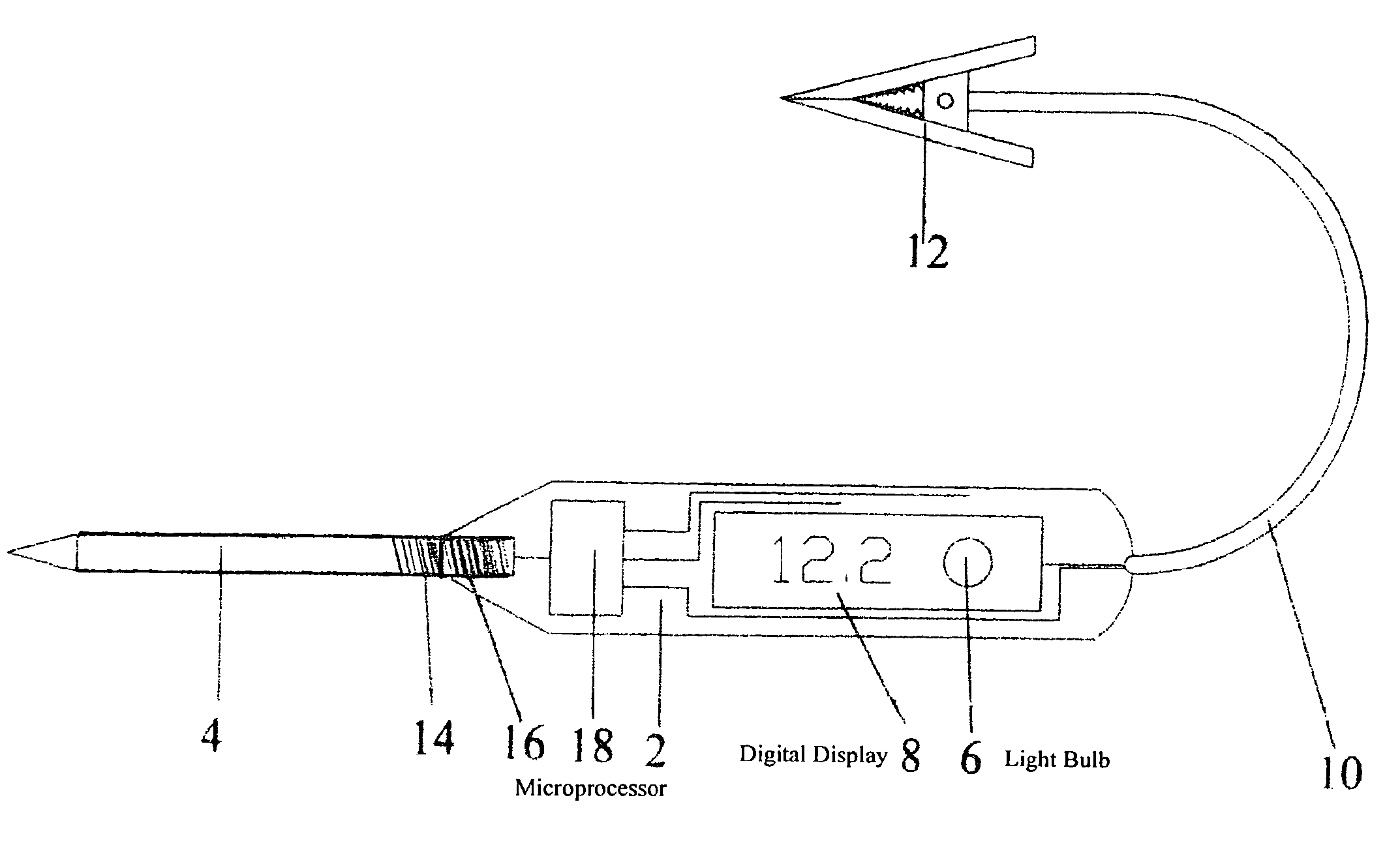
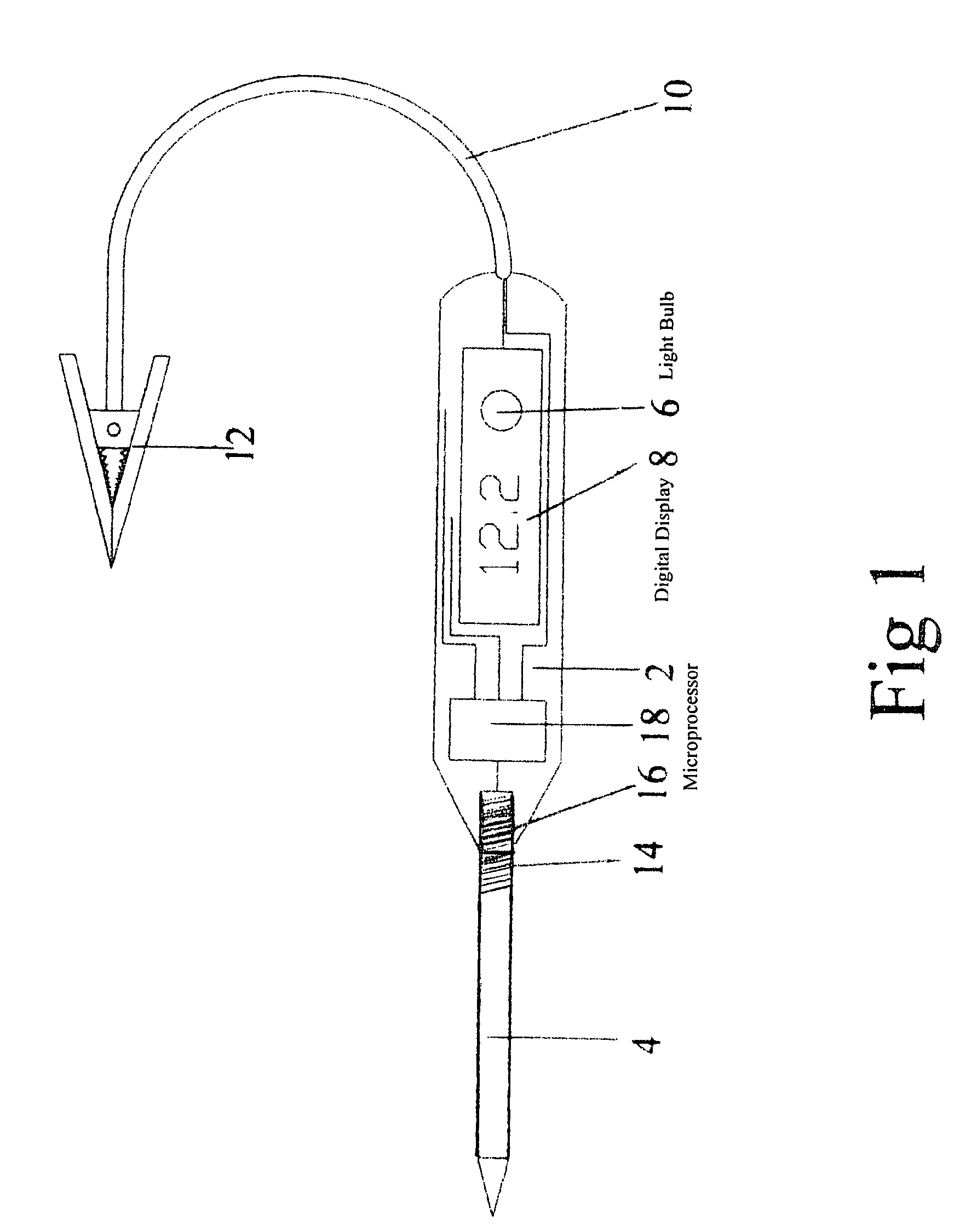
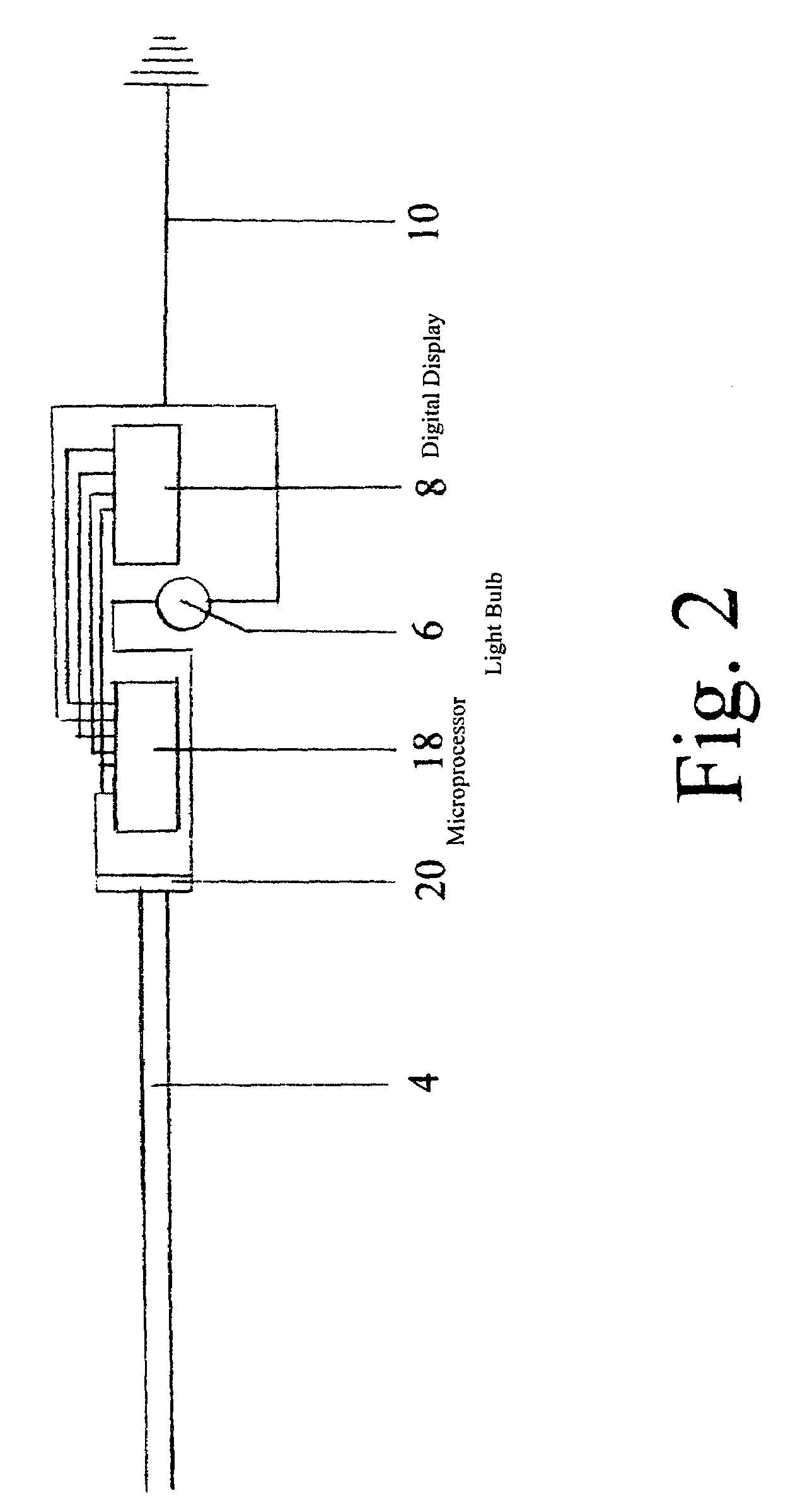
[0008]FIG. 1. The present invention consisting of a variable voltage light bulb 6 used to indicate the presents of voltage and a liquid crystal digital read out display 8 used to display a digital read out of the measurement of voltage present, with both the light bulb 6 and volt meter display 8 being incorporated inside a main body housing handle 2. Attached to the main body housing handle 2 is a metal, voltage conducting probe 4 with a tapering tip coming to a shape point at one end of the probe 4. This allows penetration into a common electrical wire outer protective installation coating and also provides a path for the electrical voltage to flow from the wire metal core to the micro voltage processor chip 18. The micro voltage processor chip 18 is used to transfer a signal of both the presence of voltage to the variable voltage light bulb 6 and the amount of voltage to the digital read out volt meter display 8. In order to activate the testing probe a complete electrical circuit...


PUM


Abstract

The present invention relates to a quick reference electrical voltage testing tool utilizing a variable voltage range light bulb and digital read out voltage meter both incorporated in the testing tool's handle. The variable voltage range light bulb indicates to the user the knowledge of voltage present and the digital voltage read out indicates the measured amount of voltage available to the tested component. This allows for a faster diagnosis of an electrical problem particularly when voltage sensitive components are being tested. When testing electrical components for non-operation, this quick reference tool will allow a much quicker diagnoses of an electrical problem without the need of a voltage meter.

Description

BACKGROUND OF INVENTION[0001]1. Field of the Invention[0002]This invention relates to a quick reference tool used to test 12 volt direct current electrical voltage and primarily designed for automotive applications.[0003]2. Background of the Related Art[0004]Commonly used today for electrical testing is a quick reference 12 volt test light probe equipped with a variable voltage light bulb. The light bulb having a variable range from 7 to 16 volts indicates electrical power to an electrical component however, the exact amount of voltage is not indicated and the amount of voltage could be too little or too much to operate the component. As an example most vehicles today use multi voltage electrical components in the operation of the vehicle. While most automotive vehicles utilize a 12 volt direct current systems many electrical components operate on lesser voltage such as the on board computer and sensors. The sensors are used to relay messages back to the computer for changing engine...

Claims


Application Information

Patent Timeline
Patent Type & Authority Patents(United States)
IPC IPC(8): G01R31/02G01R27/08
CPCG01R1/06788G01R19/16561G01R19/2503
Inventor WILFERD, RANDELL LEE
Owner WILFERD RANDELL LEE
Learn More