Loading dock door seal

a technology for loading docks and doors, applied in the field of loading docks, can solve the problems of difficult or impossible to secure the frame and seal in the mount, even exteriors pose difficulties in installation, and ridges often obscure the side of the mounting

Inactive Publication Date: 2008-06-10
CHALFANT SEWING FABTORS
View PDF37 Cites 15 Cited by
  • Summary
  • Abstract
  • Description
  • Claims
  • Application Information

AI Technical Summary

Benefits of technology

[0007]The present invention is directed to a seal structure that facilitates improved sealing between a truck, or trailer, and a loading dock doorframe. In accordance with a first aspect of the present invention, a seal system is provided. The seal system includes one or more dock pads. The dock pad(s) includes a backing structure having a front portion and an opposing rear portion; a first foam layer coupled to the rear portion of the backing structure to provide a seal between a building surface and the dock pad; and a second foam layer coupled to the front portion of the backing structure to provide a seal between the dock pad and a vehicle.
[0010]In accordance with yet another aspect of the present invention, a seal system includes means for providing a substantially airtight seal between a dock pad and a building surface; means for providing a seal or a substantially airtight seal between the dock pad and a rear portion of a vehicle; and means for providing rigidity to the dock pad.

Problems solved by technology

While door seals are easily installed on smooth-sided buildings, buildings with uneven exteriors pose difficulties in installation.
This is generally needed because the ridge interferes with the mounting of a bracket used to hold the mounting in place.
Even if a seal mount can be attached without cutting the ridge, for example, by welding the mount instead of using fastening brackets, the ridge often obscures the side of the mounting.
In such an occluded position, it becomes difficult or impossible to secure the frame and seal in the mount by usual methods, for example, by passing lag screws through the side of the mount and into the frame.

Method used


Image

  • Loading dock door seal
  • Loading dock door seal
  • Loading dock door seal

Examples


Embodiment Construction

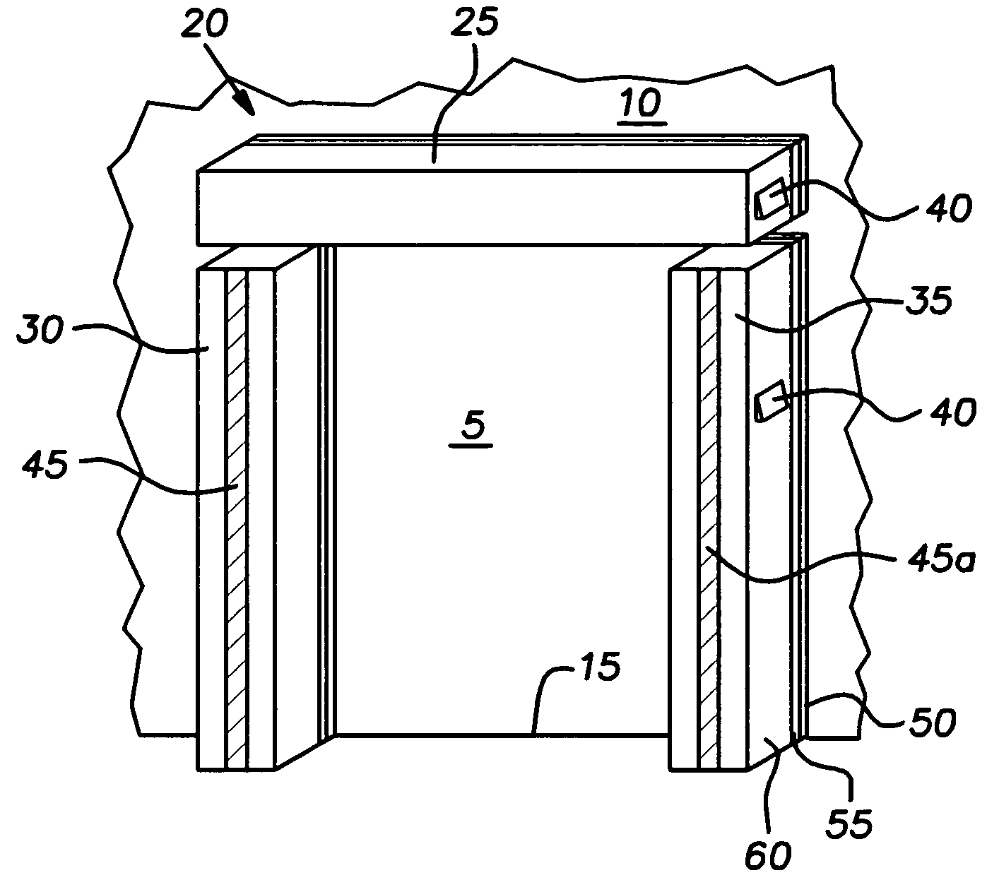
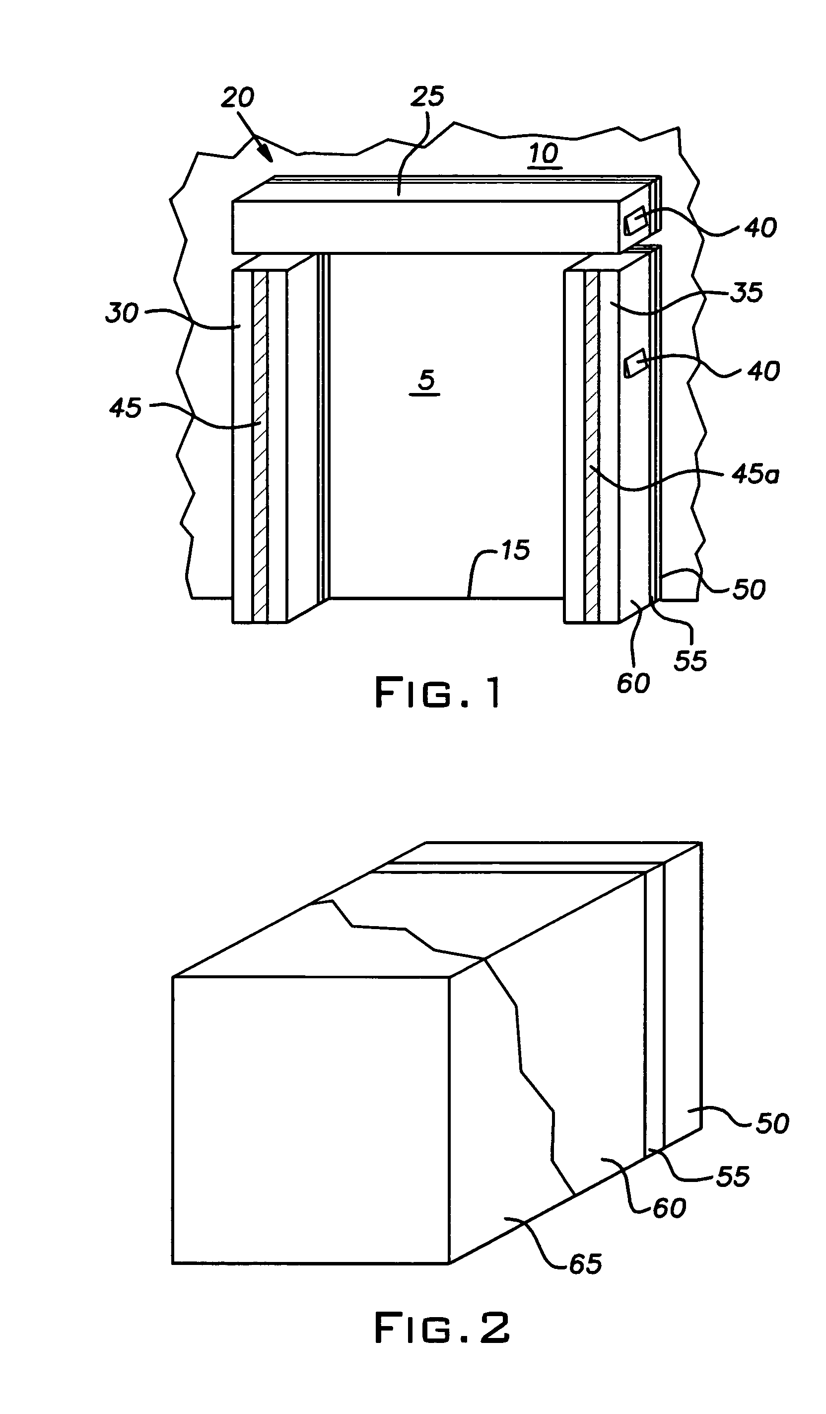
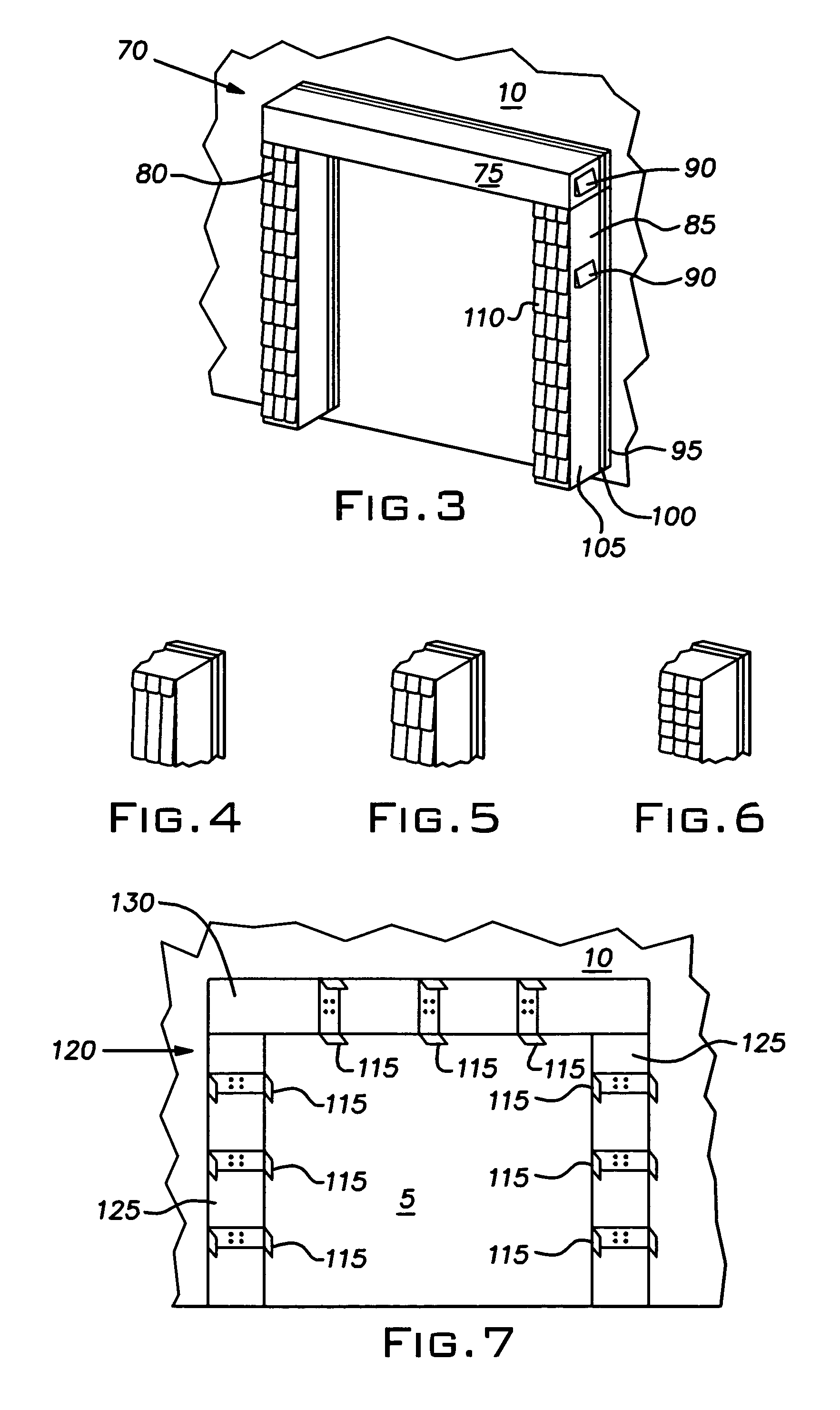
[0032]The present invention relates to a seal system for a loading dock. The present invention will now be described with reference to the drawings, wherein like reference numerals are used to refer to like elements throughout. It is to be appreciated that the various drawings are not drawn to scale from one figure to another nor inside a given figure, and in particular that the size of the components are arbitrarily drawn for facilitating the reading of the drawings. In the following description, for purposes of explanation, numerous specific details are set forth in order to provide a thorough understanding of the present invention. It may be evident, however, that the present invention may be practiced without these specific details. In other instances, well-known structures and devices are shown in block form in order to facilitate describing the present invention.

[0033]In accordance with an aspect of the present invention, a seal system is provided that can be employed with fla...


PUM


Abstract

A seal system is utilized with flat, rough, and / or ribbed wall surfaces and includes a top dock pad and two substantially parallel side dock pads, which substantially frame a doorway at a loading dock. The dock pads are secured to the wall by a plurality of mounting brackets. The dock pads include a first foam layer coupled to a rear portion of a backing structure. The first foam layer operates to accommodate, or substantially “fill-in”, any surface irregularities of the building wall surface, such as a rough wall texture and rib surfaces, to provide an airtight or substantially airtight seal between the building and the seal structure. The dock pads also include a second foam layer coupled to a front portion of the backing structure. The second foam layer is employed to create an effective seal between the building and a rear portion of a vehicle.

Description

[0001]This application claims the benefit of U.S. Provisional Patent Application Ser. No. 60 / 525,619 filed Nov. 26, 2003.TECHNICAL FIELD[0002]The present invention generally relates to loading docks. In particular, the present invention relates to systems and methods for a loading dock door seal.BACKGROUND OF THE INVENTION[0003]Loading docks are common features of warehouses, retail stores, and other structures where trucks load and unload cargo. A typical loading dock has an opening ranging from 6 to 9 feet in width and 7 to 13 feet in height. A rubber bumper is typically placed along the bottom side of the opening to mitigate damage to the cargo body when trucks or trailers back up to the loading dock.[0004]While the rubber bumper ensures that the cargo body does not come in contact with the building, it also creates gaps between the side and top walls of the cargo body and the building structure. Left unblocked, these gaps may allow environment effects, such as heat, cold, rain, ...

Claims


Application Information

Patent Timeline
Patent Type & Authority Patents(United States)
IPC IPC(8): E04D13/18B65G69/00E04B1/62
CPCB65G69/008
Inventor CHALFANT, JEFFREY R.
Owner CHALFANT SEWING FABTORS
Why Eureka
Try Eureka