
Backlight assembly with excellent light efficiency and display device having the same

a backlight assembly and display device technology, applied in the direction of instruments, lighting support devices, mould pallets, etc., can solve the problems of decreased brightness in the center region of the display area, increased thickness of the lcd device, and optical loss, and achieve the effect of improving light efficiency

Active Publication Date: 2008-05-27
SAMSUNG DISPLAY CO LTD
View PDF23 Cites 8 Cited by
  • Summary
  • Abstract
  • Description
  • Claims
  • Application Information

AI Technical Summary

Benefits of technology

The present invention provides a backlight assembly and display device with improved light efficiency for visibility. The backlight assembly includes a plurality of light sources arranged in parallel to each other and a fixing member. When a display area is divided by the light sources, the average area of the display area sections between adjacent light sources is less than or equal to the area of the display area section between the outermost light source and the edge of the display area. The backlight assembly also includes a reflecting member and an inner side surface of the fixing member that is inclined. The display device includes a panel unit displaying an image and the backlight assembly. The technical effects of the invention include improved light efficiency, reduced power consumption, and improved display quality.

Problems solved by technology

In this case, unnecessary light is concentrated on the edges, thereby causing optical loss.
However, this causes an increased thickness of the LCD device.
When the light sources are disposed adjacent to the edges of the display area, the light sources are spaced further apart from each other in the center region of the display area, thereby causing a problem of decreased brightness at the center region of the display area.

Method used


Image

  • Backlight assembly with excellent light efficiency and display device having the same
  • Backlight assembly with excellent light efficiency and display device having the same
  • Backlight assembly with excellent light efficiency and display device having the same

Examples


experimental example 1

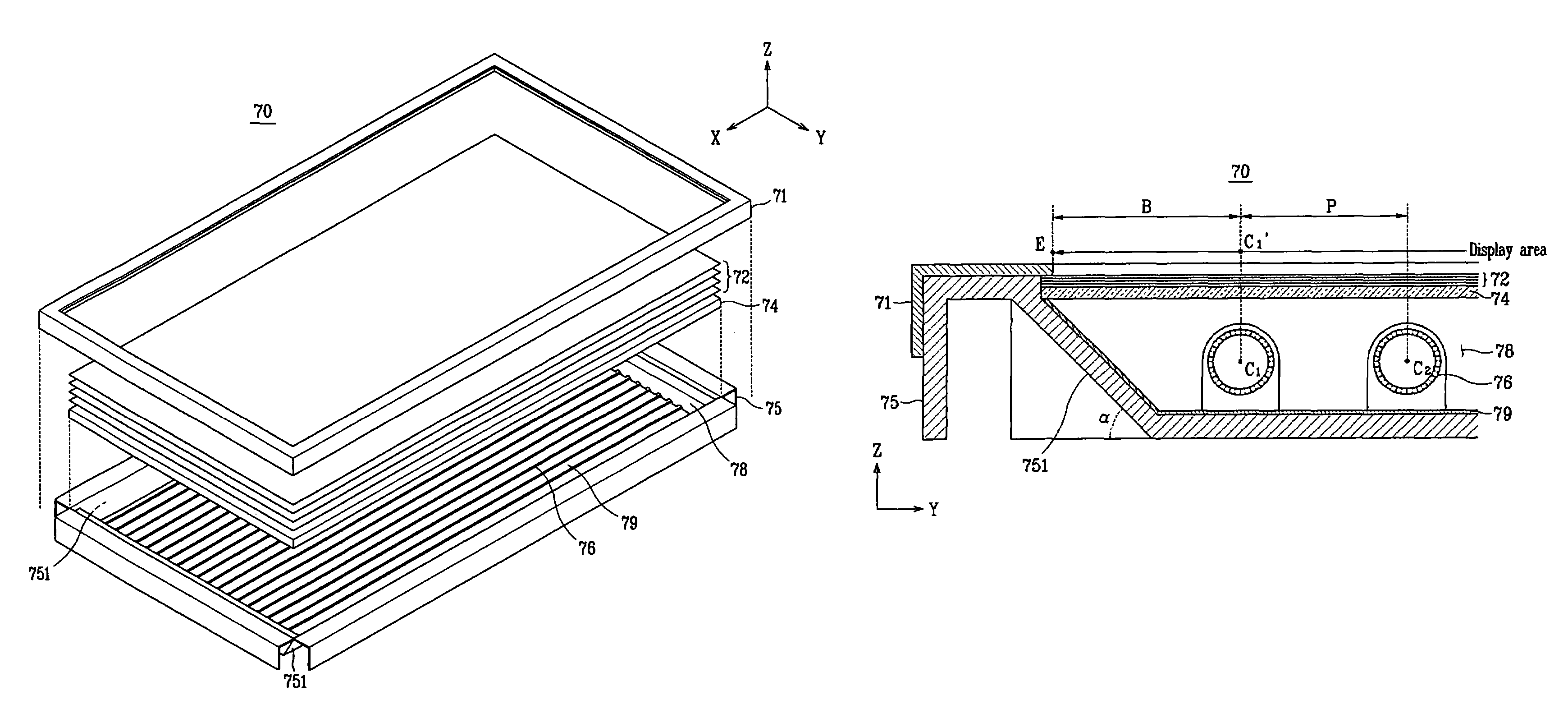
[0086]A 32-inch LCD panel is prepared. The number of lamps used in the experimental example is sixteen. The distance B as shown in FIG. 4 is set to 23.6 mm and the pitch P is set to 23.0 mm. A driving power is applied to the lamps arranged in the above-mentioned fashion. The brightness of the display area is measured in the width direction of the lamps, from a first side of the display area defined by edge E to an opposite side of the display area defined by an opposite edge E. The experimental result is indicated by a thick solid line in FIG. 8.

experimental example 2

[0087]A 40-inch LCD panel is prepared. The number of lamps used in the experimental example is twenty. The distance B as shown in FIG. 4 is set to 25.6 mm and the pitch P is set to 23.5 mm. A driving power is applied to the lamps arranged in the above-mentioned fashion. The brightness of the display area is measured in the width direction of the lamps, from a first side of the display area defined by edge E to an opposite side of the display area defined by an opposite edge E. The experimental result is indicated by a thin solid line in FIG. 8.


PUM

PropertyMeasurementUnit
distanceaaaaaaaaaa
inclination angleaaaaaaaaaa
distanceaaaaaaaaaa

Abstract

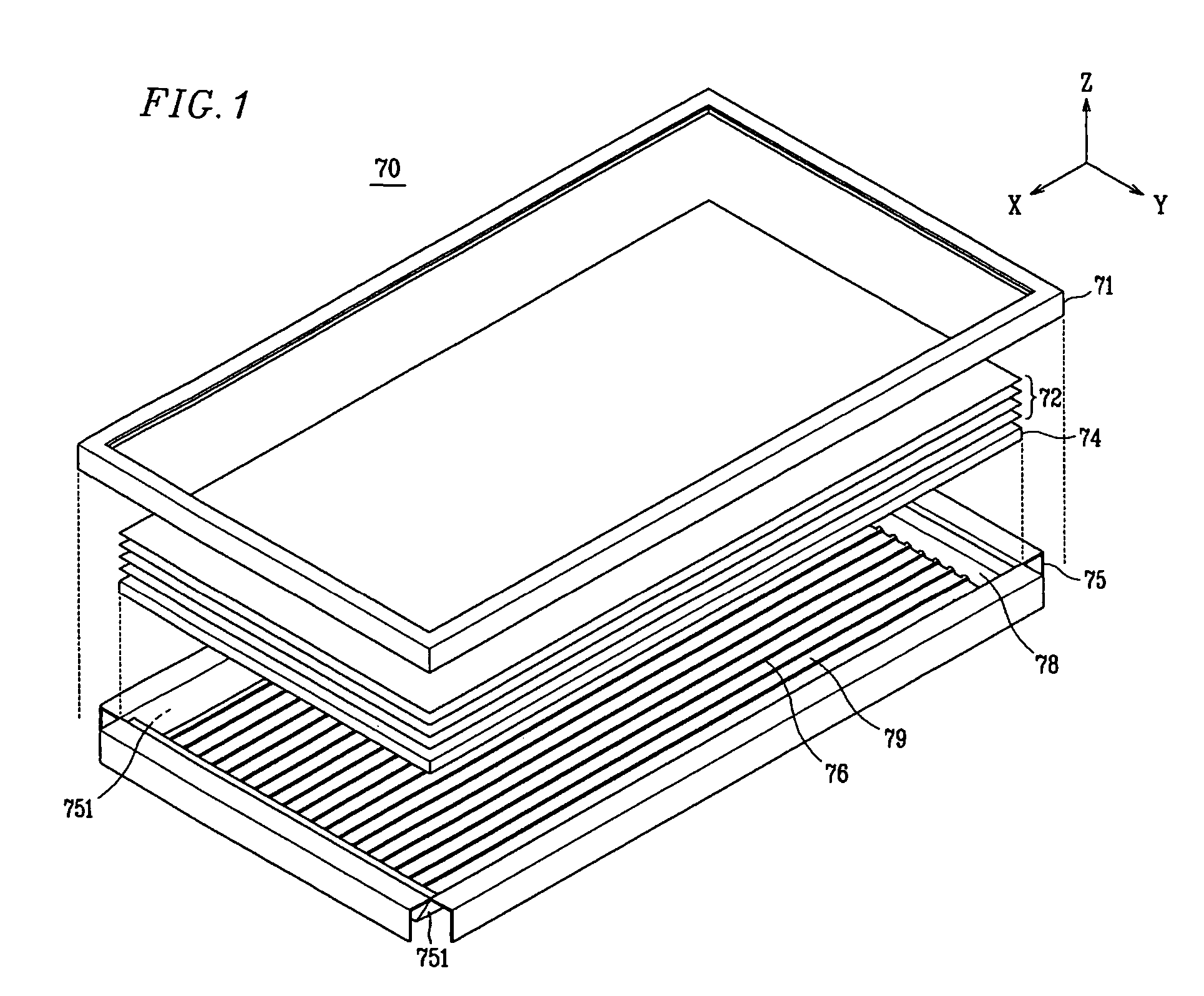
A backlight assembly with excellent light efficiency and a display device provided with the backlight assembly is provided where the backlight assembly includes a plurality of light sources longitudinally arranged in parallel to each other, and a fixing member receiving the plurality of light sources. When a display area, formed by light emitted from the plurality of light sources, is divided by the plurality of light sources into a plurality of display area sections, an average area of the display area sections between light sources adjacent to each other is less than or equal to an area of a display area section between an edge of the display area and the light source most adjacent thereto.

Description

[0001]This application claims priority to Korean Patent Application No. 2005-0019516, filed on Mar. 9, 2005 and all the benefits accruing therefrom under 35 U.S.C. §119, and the contents of which in its entirety are herein incorporated by reference.BACKGROUND OF THE INVENTION[0002](a) Field of the Invention[0003]The present invention relates to a backlight assembly with excellent light efficiency and a display device provided with the backlight assembly, and more particularly, the present invention relates to a backlight assembly with light efficiency enhanced by changing an arrangement of light sources and a display device provided with the same.[0004](b) Description of the Related Art[0005]Due to recent developments in semiconductor technologies, the demand for display devices having small size, small weight, and high performance has increased dramatically.[0006]Liquid crystal display (“LCD”) devices have advantages such as small size, small weight, and low power consumption. Ther...

Claims


Application Information

Patent Timeline
Patent Type & Authority Patents(United States)
IPC IPC(8): A47F3/00F21S2/00F21Y101/00F21Y103/00G02F1/13357
CPCG02F1/133611G02F1/133608B28B7/0097B28B1/0873B28B7/162B28B7/0055B28B7/241E02D29/02
Inventor KANG, JUNG-TAEKWON, YOON-SOOCHANG, WOONG-JAE
Owner SAMSUNG DISPLAY CO LTD
Learn More