Control method and apparatus

a control method and control apparatus technology, applied in the direction of electric controllers, ignition automatic control, instruments, etc., can solve the problems of deterioration of controllability, affecting the operation of the control system, and increasing the essentially of the inter-loop interference of the artificial intelligence,

Inactive Publication Date: 2008-05-20
YAMATAKE HONEYWELL CO LTD
View PDF5 Cites 19 Cited by
  • Summary
  • Abstract
  • Description
  • Claims
  • Application Information

AI Technical Summary

Benefits of technology

[0029]The present invention has been made in consideration of the above problems and, has as its object to provide a control method and apparatus which can prevent integration windup in a control system designed to change an absolute quantity such as the mean value of a plurality of state quantities to a desired value while maintaining the relative quantity between a plurality of state quantities at a desired value, and allow a conventional parameter adjustment method, automatic adjustment function, and the like to be applied to the control system.

Problems solved by technology

If, therefore, the state quantity transformation unit is simply applied to the control apparatus, the artificial inter-loop interference essentially tends to increase.
This tends to cause a deterioration in controllability.
If a controller such as a PID controller gives no consideration to the physical upper and lower limits of an actuator, the integration windup problem arises.
However, since the heater output saturates at 100%, an increase in the measured temperature value PV with an increase in heater output reaches its limit.
This causes a long delay in the start of temperature drop.
For this reason, in the control apparatus shown in FIG. 57, integration windup problem similar to that in the above PID controller may arise.
That is, this does not meet the basic condition that a controller, actuator, controlled system, and measurement means should physically correspond to each other.
Therefore, any conventionally proposed adjustment method or automatic adjustment function cannot be applied to the control apparatus shown in FIG. 57, and it is very difficult to realize parameter adjustment for a controller such as PID parameter adjustment.

Method used


Image

  • Control method and apparatus
  • Control method and apparatus
  • Control method and apparatus

Examples


first and second embodiments

Principles of First and Second Embodiments

[0090]In the first and second embodiments described below, an absolute state quantity serving as a reference such as a state quantity mean value will be referred to as a reference state quantity, and a state quantity controlled to maintain a relative quantity (e.g., a state quantity difference) with respect to the reference state quantity at a specified value will be referred to as a follow-up state quantity. In addition, a set point for the reference state quantity will be referred to as a reference state quantity set point; the measurement value of the reference state quantity, a reference state quantity measurement value; a set point for a follow-up state quantity, a follow-up state quantity set point; the measurement value of a follow-up state quantity, a follow-up state quantity measurement value; a set point for the relative quantity between the reference state quantity and a follow-up state quantity, a follow-up state quantity relativ...

first embodiment

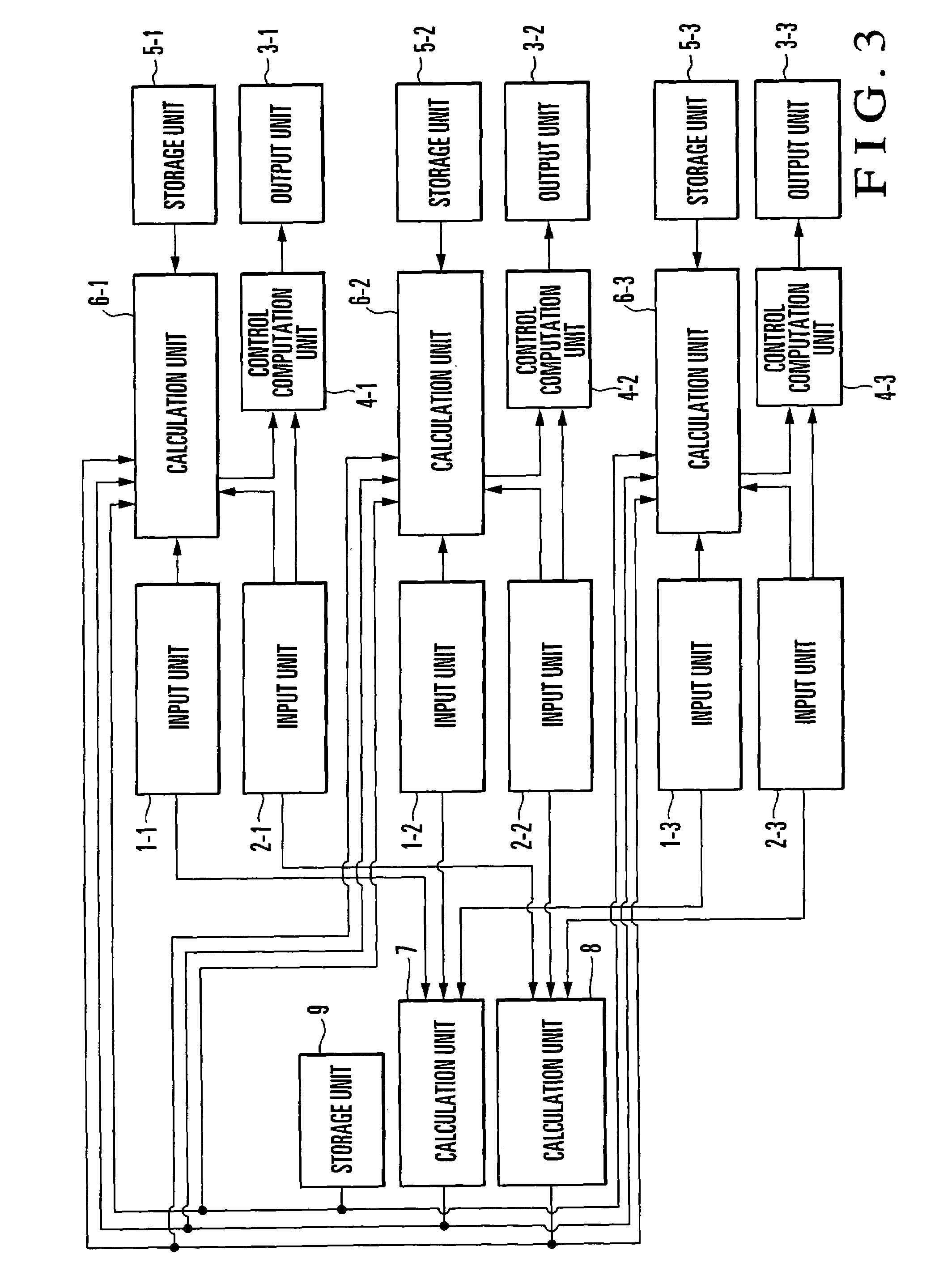
[0115]The first embodiment of the present invention will be described in detail below with reference to the accompanying drawings. FIG. 3 shows the arrangement of a control apparatus according to the first embodiment of the present invention. This embodiment exemplifies a case wherein there are three control loops, the state quantity mean value of the three control loops is used as a reference state quantity, and the state quantities of the three control loops are used as follow-up state quantities. However, as long as there are two or more control loops, a similar control system can be formed on a similar principle.

[0116]In the control apparatus in FIG. 3, the arrangement of the first control system associated with the first follow-up state quantity comprises a follow-up state quantity set point SP1 input unit 1-1, a follow-up state quantity measurement value PV1 input unit 2-1, a manipulated variable MV1 output unit 3-1, a PID control computation unit (PID controller) 4-1, a coeff...

second embodiment

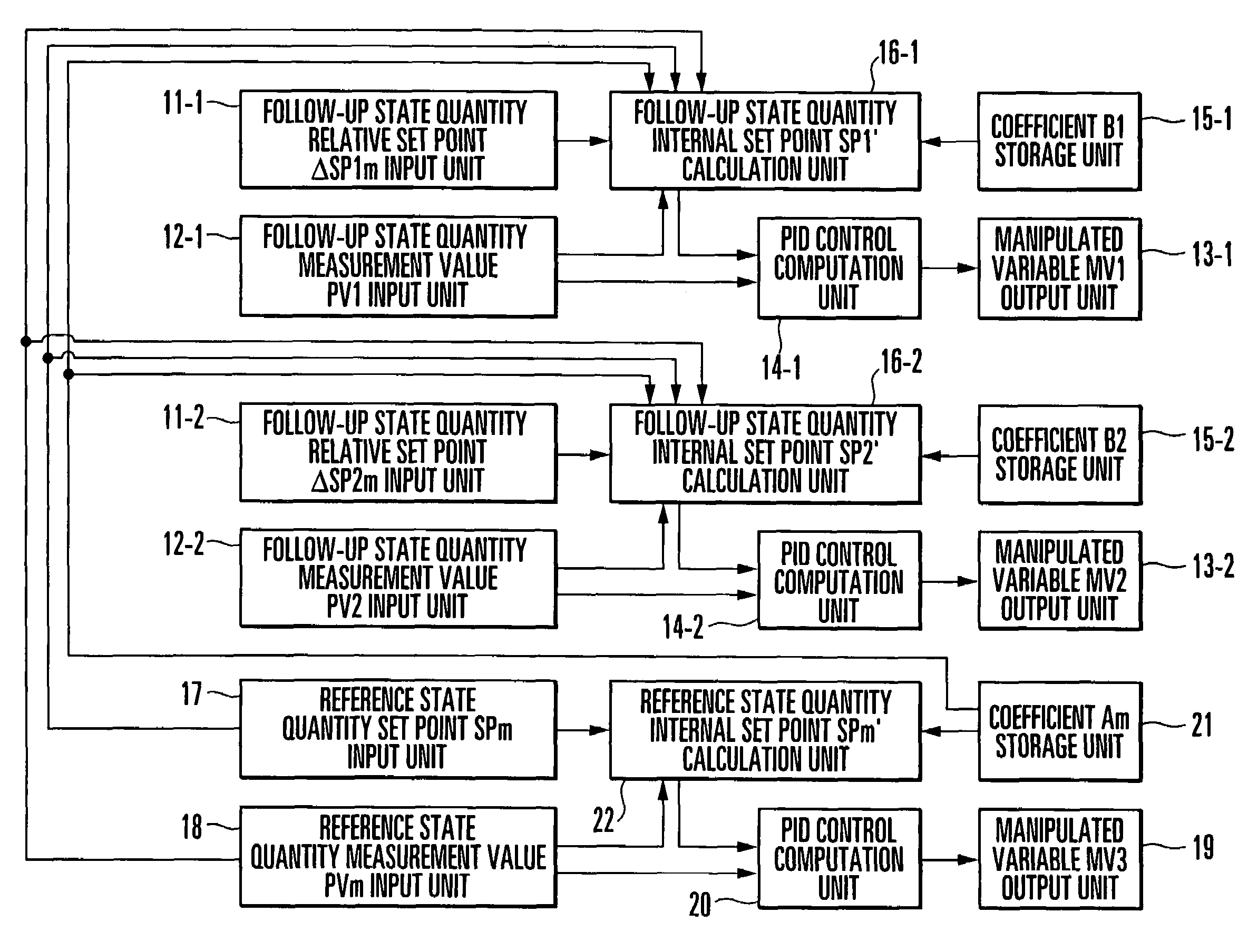
[0150]The second embodiment of the present invention will be described next. FIG. 11 shows the arrangement of a control apparatus according to the second embodiment of the present invention. This embodiment will exemplify a case wherein there are three control loops, the state quantity of one typical control loop is used as a reference state quantity, and the state quantities of the remaining two control loops are used as follow-up state quantities. However, a similar control system can be formed on the basis of the same principle as long as there are two or more control loops.

[0151]In the control apparatus in FIG. 11, the arrangement of the first control system associated with the first follow-up state quantity comprises a follow-up state quantity relative set point ΔSP1m input unit 11-1, a follow-up state quantity measurement value PV1 input unit 12-1, a manipulated variable MV1 output unit 13-1, a PID control computation unit (PID controller) 14-1, a coefficient B1 storage unit 1...


PUM


Abstract

In a control method, when a state quantity serving as a specific reference is defined as a reference state quantity, and a state quantity which is controlled to maintain a relative quantity with respect to the reference state quantity at a specified value is defined as a follow-up state quantity, one of a plurality of control computation input values input to a controller of at least two controllers respectively forming control loops, which controls the follow-up state quantity is transformed, into an internal input value, and the internal input value is input to the controller which controls the follow-up state quantity. At least the two controllers calculate manipulated variables, respectively, and the calculated manipulated variables are output to controlled systems of corresponding control loops. The internal input value is calculated by setting the internal input value as the sum of a first element for the reference state quantity and a second element for the relative quantity, an element of the control computation input value which corresponds to the reference state quantity as the first element, and a value obtained by multiplying an element of the control computation input value which corresponds to the relative quantity as the second element. A control apparatus is also disclosed.

Description

BACKGROUND OF THE INVENTION[0001]The present invention relates to a process control technique and, more particularly, to a control method and apparatus which handle, as a controlled system, a relative quantity such as a state quantity difference in a control system having at least two control loops.[0002]FIG. 53A shows the arrangement of a temperature controller as a conventional control apparatus. This temperature controller is disclosed in, for example, Japanese Patent Laid-Open No. 8-095647. Heat treatment work 1016 is loaded into a furnace 1001. A heater 1011, a detection means 1012 for detecting a control temperature TC1, a detection means 1013 for detecting a surface temperature TC2 of the work 1016, and a detection means 1014 for detecting a deepest temperature TC3 of the work 1016 are arranged in the furnace 1001. Reference numeral 1002 denotes a power regulator. A control unit 1003 includes a comparator 1031 which compares the control temperature TC1 with an execution progr...

Claims


Application Information

Patent Timeline
Patent Type & Authority Patents(United States)
IPC IPC(8): G05B11/01G05B13/02G06F7/60G05B11/32G05B11/42
CPCG05B11/42G05B11/32G05B13/04
Inventor TANAKA, MASATO
Owner YAMATAKE HONEYWELL CO LTD
Why Eureka
Try Eureka