
Radiation shield for portable x-ray fluorescence instruments

a fluorescence instrument and radiation shielding technology, which is applied in the direction of instruments, nuclear elements, and material analysis using wave/particle radiation, etc., can solve the problems of absorbing material in the nose of the inspection instrument, unable to prevent radiation, and cannot meet the requirements of the radiation shielding inside the xrf instrument, so as to reduce radiation levels and ensure the thickness

Active Publication Date: 2008-05-20
THERMO NITON ANALYZERS
View PDF11 Cites 19 Cited by
  • Summary
  • Abstract
  • Description
  • Claims
  • Application Information

AI Technical Summary

Benefits of technology

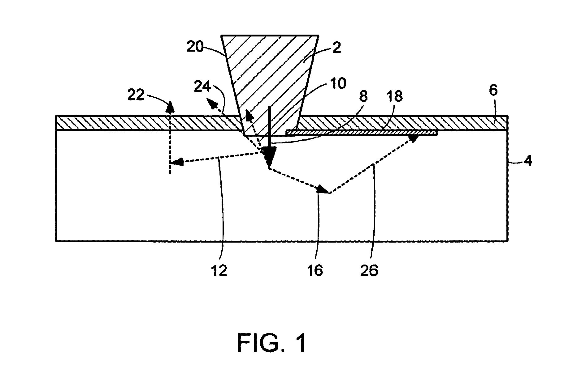
[0010]In accordance with preferred embodiments of the invention, a radiation shield is provided, consisting of a membrane containing material that absorbs ionizing radiation, the membrane being attached to the front face of the XRF instrument that emits penetrating radiation predominantly along a propagation axis and that is used for inspecting materials. The radiation shield extends outwardly from the propagation axis and may, for example, lie proximate to the walls being inspected. The membrane may be flexible enough so that it conforms to surfaces of the inspected walls and the membrane being of sufficient thickness to reduce radiation levels to below levels required for radiation safety.
[0011]More particularly, the radiation shield may reduce ambient radiation levels at a distance from a surface irradiated by penetrating radiation emanating from an instrument that has a distal end proximate to the irradiated surface and emitting the penetrating radiation predominantly along a propagation axis. The radiation shield has a platen of attenuating material having an extent substantially transverse to the propagation direction of penetrating radiation and substantially adjacent to the irradiated surface.

Problems solved by technology

That requirement cannot be satisfied with the shielding inside an XRF instrument.
The absorbing material in the nose of the inspection instrument, however, cannot prevent radiation that is multiply scattered such that it emerges from the target in a place and direction in such a way as to not intersect the nose of the instrument.

Method used


Image

  • Radiation shield for portable x-ray fluorescence instruments
  • Radiation shield for portable x-ray fluorescence instruments
  • Radiation shield for portable x-ray fluorescence instruments

Examples


Embodiment Construction

[0018]In accordance with embodiments of the present invention, and as described now with reference to FIG. 1, shielding in the form of a collar is used to prevent multiple scattered x-rays from exiting the wall relatively far from the XRF instrument with sufficient intensity to exceed regulatory limits.

[0019]To fully appreciate why the present invention is needed and how it must be designed we need to understand the origin of the ambient radiations that result when a beam of x-rays enters material and gets Compton scattered.

The Physics of Ambient Radiation

[0020]The following discussion refers particularly to an XRF instrument used for lead paint analysis, however it should be appreciated that the conclusions drawn, and the invention described, are applicable to a wide group of applications, especially the XRF analysis of soils and plastics.

[0021]The energies of the x-rays that fluoresce lead are typically in the 20 keV range when the L x-rays of lead at 10.5 keV and 12.6 keV are use...


PUM

PropertyMeasurementUnit
atomic numberaaaaaaaaaa
diameteraaaaaaaaaa
distanceaaaaaaaaaa

Abstract

A radiation shield and method for reducing ambient radiation levels at a distance from a surface irradiated by penetrating radiation emanating from an instrument substantially along a propagation axis. The shield attaches to an end of the instrument proximate to an irradiated surface and has a surface of attenuating material disposed with a component extending outward from the propagation axis of penetrating radiation and substantially adjacent to the irradiated surface.

Description

[0001]The present application is a Continuation-in-Part of U.S. patent application Ser. No. 10 / 852,337, filed May 24, 2004, now allowed, which claims priority from U.S. Provisional Patent Application Ser. No. 60 / 472,674, filed May 22, 2003, as does the present application. The foregoing applications are incorporated herein by reference.TECHNICAL FIELD[0002]The present invention relates to methods and devices for minimizing ambient radiation when a portable x-ray instrument is taking measurements.BACKGROUND ART[0003]X-ray fluorescence (XRF) instruments measure properties of material by irradiating the material with x-rays or gamma rays and analyzing the fluorescent radiation to determine specified properties. The term “x-rays”, as used herein and in any appended claims, refers to radiation that is generated either by radioactive sources, or by instruments such as x-ray tubes, and encompasses within the term all forms of penetrating radiation including gamma rays. The specified proper...

Claims


Application Information

Patent Timeline
Patent Type & Authority Patents(United States)
IPC IPC(8): G01N23/223
CPCG01N23/223G01N2223/076
Inventor MARTIN, KENNETH P.HONNELLIO, ANTHONYGRODZINS, LEE
Owner THERMO NITON ANALYZERS
Learn More