[0043]An additional advantage of the invention includes providing an improved coating architecture for certain commonly used monoliths. For monoliths containing channels with a rectangular or square shape, the first, i.e., bottom, layer effectively rounds off the corners thus creating a more effective coating surface for subsequent layers, such as the oxygen storage component layer and the catalytic layers containing platinum group metals as catalytic agents, that are coated on top of the bottom layer. The rounding-off of the corners is illustrated in FIG. 6 and is discussed in greater detail below. The second layer can be adhered directly on the bottom layer and a catalytic layer including a PGM catalytic agent, for example, can be adhered directly on the second layer. The rounded corners prevent the catalyst washcoat from deposition in the corners where it is less accessible for contacting the exhaust gas. Due to the increased accessibility of the catalytic layer to the exhaust gas, a thinner washcoat of the catalytic layer can be used in the catalyst without sacrificing TWC catalyst performance. The thinner catalytic layer is formed from washcoat compositions having lower solids content than catalyst washcoat compositions used in preparing conventional TWC catalysts. This feature significantly reduces platinum group metal use and cost without sacrificing TWC efficiency.
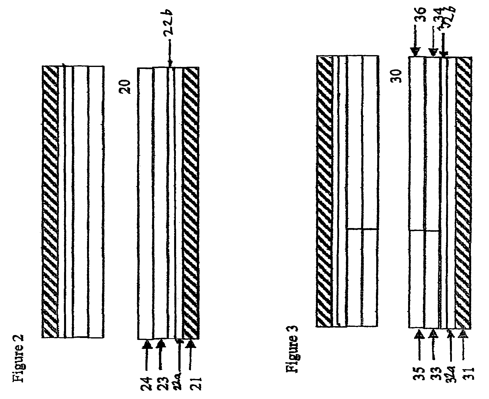
[0044]FIG. 2 depicts a layered composite of the invention having a single channel (20). A discrete coat of the bottom layer (22a) comprising substantially only a refractory metal oxide is coated as a “washcoat” onto carrier wall (21). Thereafter, a discrete coat of the second layer (22b) comprising substantially only at least one oxygen storage component and at least one binder therefor is coated as a washcoat onto the surface of layer (22a). Subsequently, a discrete coat of the third layer (23) comprising a catalytic material is coated as a washcoat onto the surface of second layer (22b) and a discrete coat of the fourth layer (24). The optional overcoat layer that may be coated as a discrete layer on the surface of layer (24) is not depicted in FIG. 2. The bottom layer (22a) would be coated on and adhered to the carrier wall (21). The second layer (22b) would be adhered to the bottom layer (22a). The third layer (23) overlying and adhering to the second layer (22b) and the fourth layer (24) overlying and adhering to the third layer (23) would be provided in one zone. With this arrangement, the gas being contacted with the catalyst, e.g., being flowed through the passageways of the catalytic material-coated carrier, will first contact the fourth layer (24), pass therethrough in order to contact the third layer (23), thereafter contacting the second layer (22b) and then lastly will contact the bottom layer (22a). The multi-layered composite depicted in FIG. 2 can be located in a close-coupled position or, alternatively, in an underbody position.
[0045]In an alternative configuration, the fourth layer need not overlie the third layer but can be provided in an upstream first zone (as sensed in the direction of gas flow through the catalyst composition) portion of the carrier, with the third layer provided on a downstream second zone portion with both zones supported on the second layer which in turn is supported on the bottom layer. In order to apply the washcoat in this configuration, an upstream first zone longitudinal segment only of the carrier (which had been previously coated with the bottom and the second layers) would be dipped into a slurry of the fourth layer of catalytic material, and dried, and the downstream second zone longitudinal segment of the carrier would then be dipped into a slurry of the third layer of catalytic material and dried.
[0046]Another preferred catalyst of the invention is a multi-zoned, multi-layered composite. As is shown in a channel (30) of this catalyst depicted in FIG. 3, this catalyst has a bottom refractory metal oxide layer (32a) overlying and adhering to the carrier wall (31), preferably of a honeycomb carrier, a second oxygen storage component+binder layer (32b) on top of and adhering to the bottom layer, a third catalytic layer on top of and overlying and adhering to the second layer and a fourth catalytic layer overlying and adhering to the third layer. Each third and fourth catalytic layer contains two zones, an upstream and a downstream zone. The second upstream zone (35) overlies and adheres to the first upstream zone (33), and the second downstream zone (36) overlies and adheres to the first downstream zone (34). Each of the first upstream, second upstream, first downstream, and second downstream zones are catalytic zones.
[0047]The first upstream zone contains a first upstream platinum component, a first upstream palladium component, and a first upstream refractory metal oxide support. The first downstream zone has a first downstream platinum component, a first downstream rhodium and a first downstream refractory metal oxide support. The second upstream zone includes a second upstream platinum component, a second upstream rhodium component, and a second upstream refractory metal oxide support. The second downstream zone has a second downstream platinum component, a second downstream palladium component and a second downstream refractory metal oxide support. The upstream and downstream zones can be reversed if hydrocarbon conversion has the higher priority than NOx conversion.
[0048]FIG. 4 shows generally at 10 a catalyst carrier illustrating a preferred embodiment of the present invention. The carrier is seen to be monolithic and of generally cylindrical shape having a cylindrical outer surface 12; one end face (inlet) 14 and an opposite end face, not visible in FIG. 4, which is identical to end face 14. The juncture of outer surface 12 with the opposite end face at its peripheral edge portion is indicated at 14′ in FIG. 1. Carrier 10 has a plurality of fluid flow channels formed therein, and, since a preferred embodiment of the present invention is adapted for the treatment of engine exhaust gases, these channels are referred to as gas flow channels 16, better seen in enlarged FIG. 5. Channel walls 21 form gas flow channels 16. Gas flow channels 16 extend through carrier 10 from end face 14 to the opposite end face thereof, the channels being unobstructed so as to permit the flow of a fluid, e.g., a gas, longitudinally through carrier 10 via gas flow channels 16 thereof. As may be seen from FIGS. 5 and 6, channel walls 21 are dimensioned and configured such that gas flow channels 16 have substantially regular polygonal shape, square in the illustrate embodiment, except for fillet portions 20 which, in the illustrated embodiment, define in profile arcuate concave sections and comprise the juncture of adjacent ones of walls 18.