
Bottom lighting backlight module having uniform illumination and process for manufacturing the same

a backlight module and uniform illumination technology, applied in the field of bottom lighting backlight modules, can solve the problems of increasing the cost in comparison to an edge lighting module, difficulty in reducing the thickness of the entire backlight module b>4/b> to less than 1 cm, and achieves the effect of less surface roughness, higher temperature endurance, and less heat dissipation problems

Inactive Publication Date: 2008-05-20
NAT CHIAO TUNG UNIV +1
View PDF8 Cites 60 Cited by
  • Summary
  • Abstract
  • Description
  • Claims
  • Application Information

AI Technical Summary

Benefits of technology

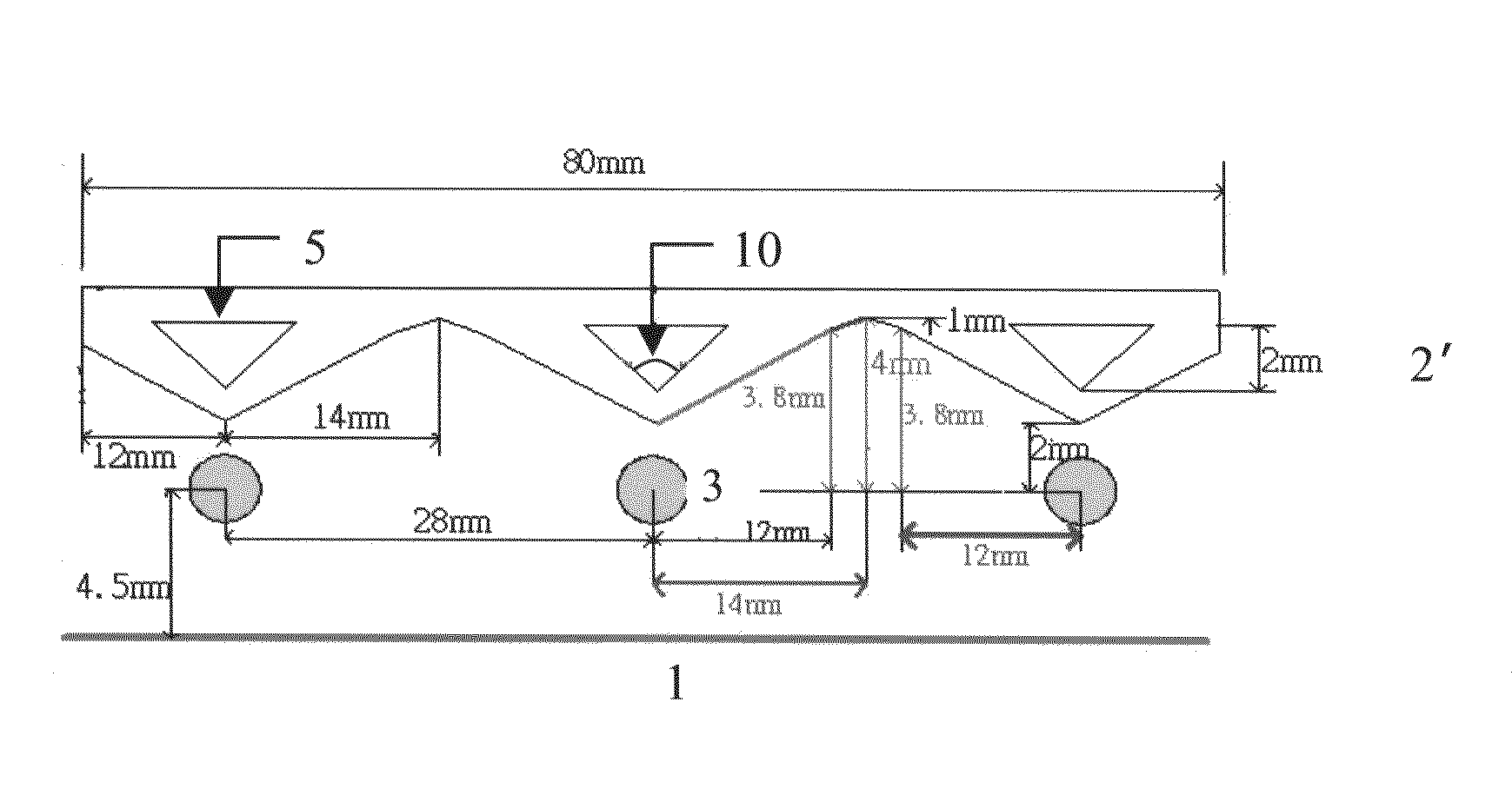
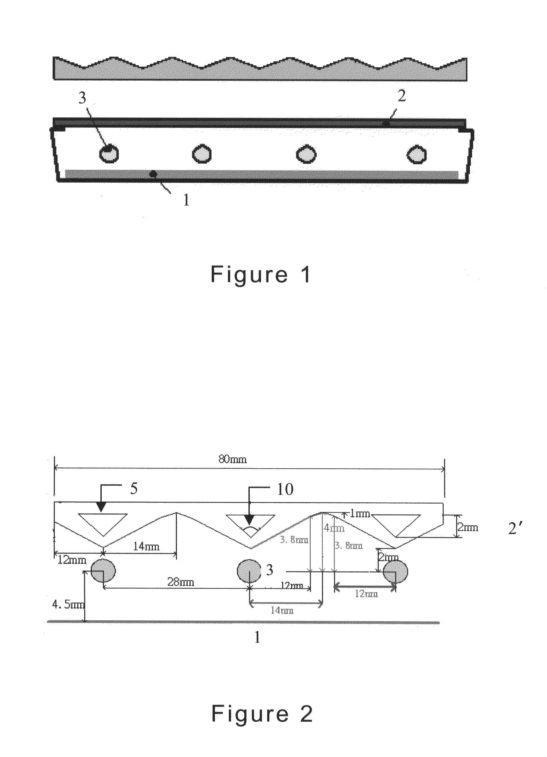
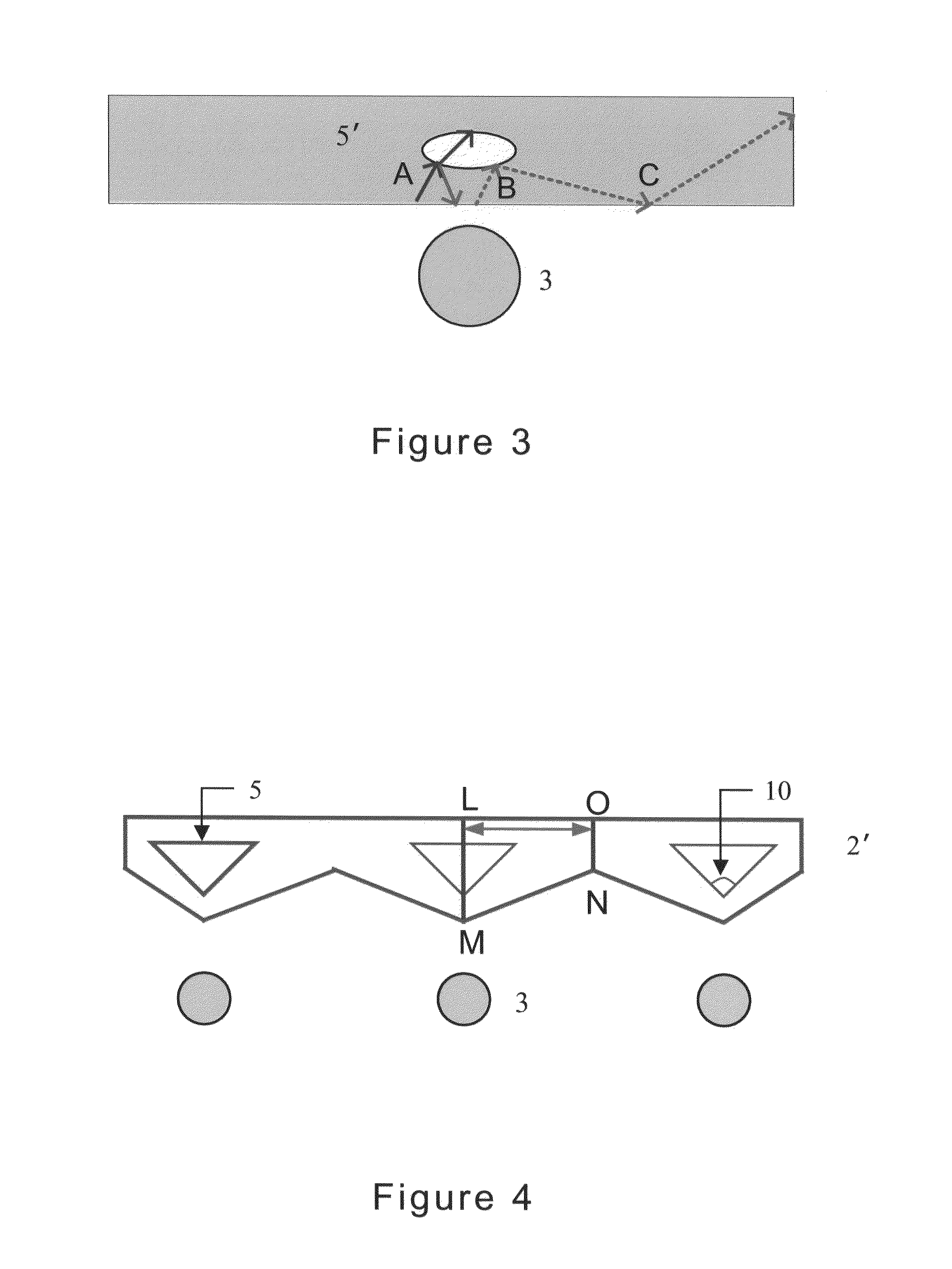
The present invention aims to improve the brightness evenness of existing backlight modules and provide a process for manufacturing a bottom lighting backlight module with reduced thickness. The invention achieves this by introducing a novel excavated structure on top of each light source that guides and redirects the light sideways, reducing the local brightness around the light source and improving the brightness evenness of the whole module.

Problems solved by technology

However, the bottom lighting backlight module needs more lamps and greatly increases the cost in comparison to an edge lighting module.
On the other hand, adding the number of lamps may result in problems on heat dissipation and power consumption, thereby making improvement on the structure design has become a key factor for the manufacturer to success in the development of new product.
Furthermore, it is difficult to reduce the thickness of entire backlight module 4 to less than 1 cm while maintaining high evenness in its brightness.
It is also difficult to achieve a brightness with evenness higher than 80% by means of a diffusion plate thicker than 2 cm.

Method used


Image

  • Bottom lighting backlight module having uniform illumination and process for manufacturing the same
  • Bottom lighting backlight module having uniform illumination and process for manufacturing the same
  • Bottom lighting backlight module having uniform illumination and process for manufacturing the same

Examples


first embodiment

Parallel Plate

[0015]FIG. 6 shows the simulation result obtained from a parallel plate made of PC. The brightness evenness obtained on the detection face 1 located on YZ plane is only 30% with the maximum flux of about 0.206 Flux / mm2, while almost no light is detected on the detection face 2 located on YZ plane which means no light is redirected to dark area.

second embodiment

Diffusion Sheet Made of PC with Triangular Excavated Structure

[0016]FIG. 7 shows the simulation result similar to FIG. 6 using a diffusion sheet made of PC with triangular excavated structure. The brightness evenness obtained on the detection face 1 is about 43% with the maximum flux of about 0.114 Flux / mm2, while the maximum flux of about 1.7 Flux / mm2 is obtained on the detection face 2 which means more lights are redirected to dark area.

third embodiment

Diffusion Sheet Made of PC with Triangular Excavated Structure

[0017]Change the apex angle 10 in FIG. 8a to 120 degree. The brightness evenness obtained on the detection face 1 is about 95% with the maximum flux of about 0.102 Flux / mm2, while the maximum flux of about 1.38 Flux / mm2 is obtained on the detection face 2 which means less lights are redirected to dark area in comparison to the case of FIG. 7.


PUM


Abstract

The present invention provides a bottom lighting backlight module comprising: a light reflecting plate, a plurality of light sources such as lamp and LED; and a diffusion sheet; wherein said diffusion sheet has an excavated structure of shape with cross-section of an inverted triangle having a specific apex angle ranging from 110 degrees to 130 degrees. Some of the light incident on the excavated structure inside the diffusion sheet can be totally reflected and redirected sideways, so that it is possible to reduce the local brightness for area around each light source but significantly improve the evenness of brightness for the whole module.

Description

FIELD OF THE INVENTION[0001]The present invention relates to a light source module device, especially to a light source module used in liquid crystal display (LCD). The light source module of present invention provides, on top of each light source, an excavated structure capable of guiding and redirecting the light sideways so as to reduce the local brightness around the light source and improve the evenness of brightness for whole module. With such structure, the present invention has achieved not only a light source module of highly uniform in brightness but also a light source module of extremely thin in thickness.BACKGROUND ART[0002]The LCD light source module is one of the critical components in LCD technology responsible for providing uniform and sufficient light on LCD panel. Since the light source module consumes more than 50% of the power in a LCD, it is a relative important subject of LCD technology to provide uniform light of desired brightness under limited power availab...

Claims


Application Information

Patent Timeline
Patent Type & Authority Patents(United States)
IPC IPC(8): F21V5/00
CPCG02F1/133504G02F1/133606G02F2001/133507G02F2001/133607G02F1/133507G02F1/133607
Inventor FENG, CHIH-HUALU, MAO-HONG
Owner NAT CHIAO TUNG UNIV
Learn More