Apparatus for treatment of snow and ice

a technology for ice and apparatus, applied in the direction of centrifugal wheel fertilisers, applications, ways, etc., can solve the problems of delayed or prolonged road treatment, insufficient capacity of traditional v-box spreaders with pre-wet systems to store, transport, and dispense liquid in sufficient quantities, so as to maximize the payload of each material, reduce the frequency of return trips, and improve the utilization of space

Active Publication Date: 2008-05-13
HENDERSON PRODS
View PDF25 Cites 46 Cited by
  • Summary
  • Abstract
  • Description
  • Claims
  • Application Information

AI Technical Summary

Benefits of technology

[0015]The storage and dispensing apparatus can be disposed within the body. The storage and dispensing apparatus can include front and rear ends, first and second side walls, and a common wall. The common wall defines a hopper for storing granular material and a liquid containment uni-body construction vessel for storing liquid. Advantageously, the common wall serves to improve the strength of the combined body while reducing weight and costs.
[0030]The present invention provides a complete integration of all required containment / storage devices, conveying systems, application systems and controls. The inventive vehicle simplifies the complexities of controlling individual components and systems for the operator, who must not only operate the equipment but also drive the vehicle, as well. In some instances, for example, the operator can be operating a front-mounted snow plow and a side-mounted (“wing”) snow plow which, combined with driving the vehicle, can require his full attention.

Problems solved by technology

While existing systems for treating snow and ice-covered roadways provide many desirable features and advantages, there remain certain problems with these combination bodies.
Space limitations of this combination of equipment tend to limit the volume of either one or both of the de-icing and anti-icing materials.
A traditional V-box spreader with a pre-wet system has insufficient capacity to store, transport, and dispense an adequate volume of liquid for anti-icing operations without sacrificing the volume of granular materials for de-icing carried on the truck.
This method results in delayed or prolonged road treatment, added fuel and operator costs, and multiple pieces of equipment.
For example, the conventional systems can also require an additional cost of manpower to convert the vehicles from non-ice control to granular and / or anti-icing modes.
Furthermore, loss of property, or even life, can occur as a result of the delays associated with the changing of the vehicle from granular to anti-icing and back again or with operators moving from one type of truck to another.
The methods of towing trailers behind dump trucks or utilizing top heavy pre-wetting tanks attached to a spreader system can pose safety hazards for operators and travelers on the roadways.
Therefore, the need to change the equipment treating the roadways depending on the weather and / or road conditions can lead to other delays.
Materials used for ice control (including cinders, sand, salt, etc.) have a tendency to bridge over the auger and therefore interrupted / disrupted material flow can result.
On the other hand, chain conveyor systems are susceptible to maintenance problems during the off-season (cold weather being typically only a few months of the year in most instances).
For example, the chain can be stationary and easily rust to the point of “freezing up,” making it un-useable the following season or requiring considerable maintenance time to free up the chain.
Furthermore, because each link of the chain moves, the chain conveyor system has a considerable number of moving parts which in turn require a corresponding amount of maintenance.
The uneven discharge flow can cause “striping” of ice control materials on the pavement and also can require the spreading of materials in amounts larger than needed to compensate for this interrupted flow characteristic.

Method used


Image

  • Apparatus for treatment of snow and ice
  • Apparatus for treatment of snow and ice
  • Apparatus for treatment of snow and ice

Examples


Embodiment Construction

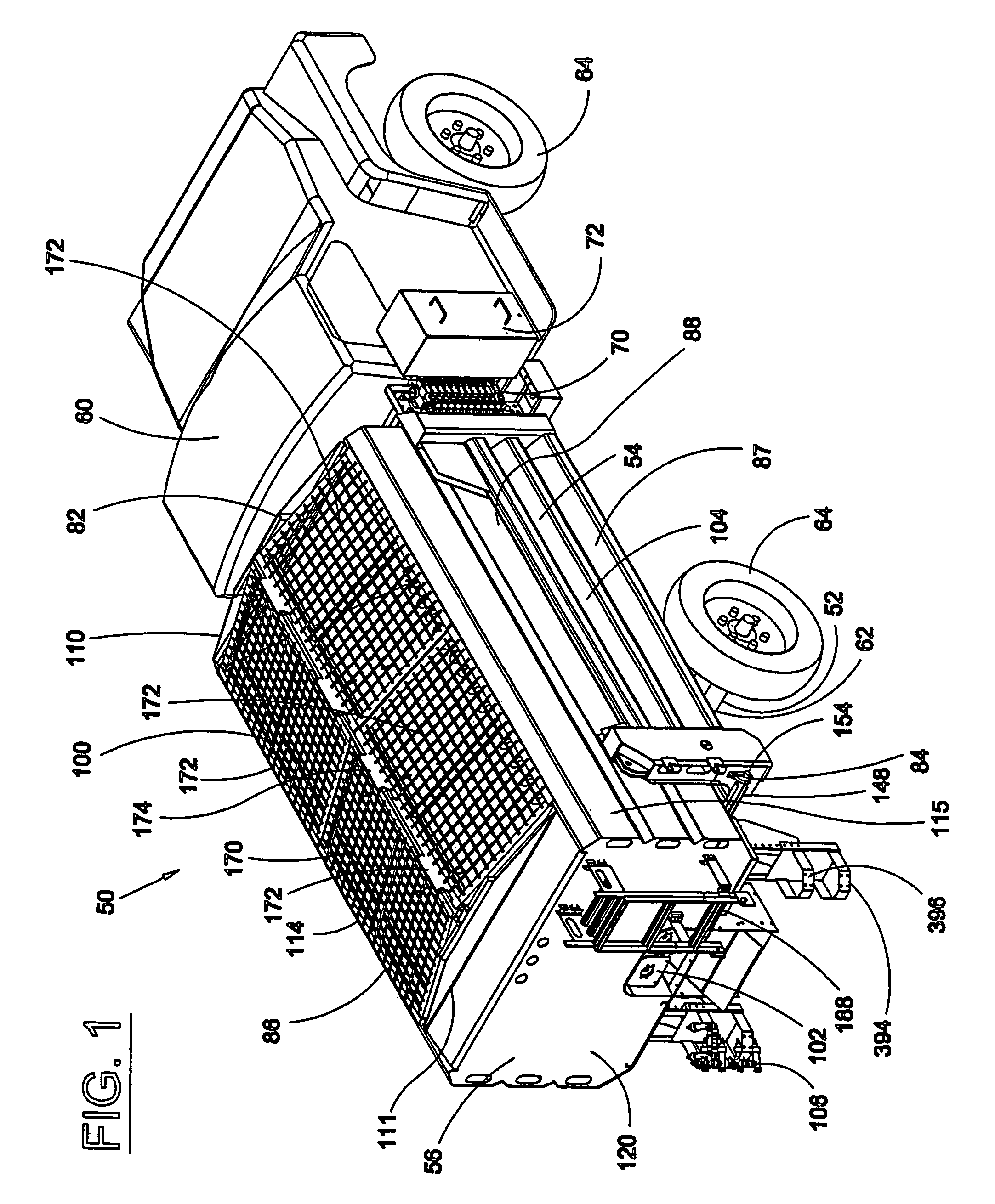
[0056]Turning now to the drawings, there is shown in FIG. 1 an illustrative vehicle 50 for treatment of snow and / or ice on a surface such as a roadway in accordance with the present invention.

[0057]Referring to FIG. 1, the vehicle 50 includes a chassis 52, a dump body 54, and a removable storage and dispensing apparatus 56 disposed within the body 54.

[0058]The chassis 52 can include a truck cab 60, a frame 62, and a plurality of wheels 64. The chassis 52 includes a valve bank 70 for controlling the hydraulic system of the vehicle. A cover 72 can be provided to enclose the valve bank 70.

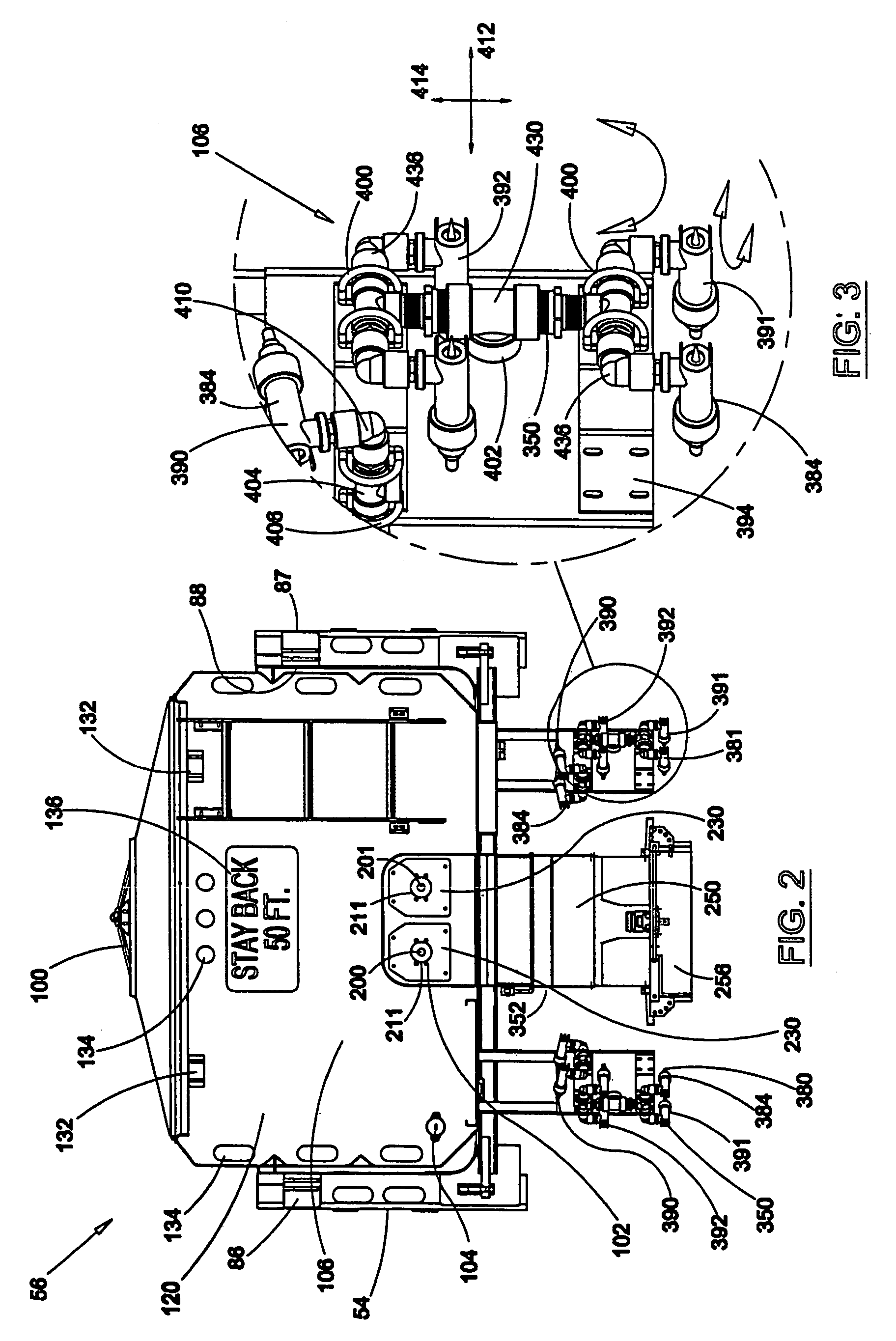
[0059]The body 54 is mounted to the chassis 52. The body 54 includes a front end 82, an open rear end 84, and first and second side walls 86, 87, as shown in FIGS. 1 and 2. The body 54 is generally U-shaped, as shown in FIG. 2. The dump body 54 defines a cavity 88 for storing materials, such as gravel, dirt, brush or the like. The dump body 54 can be pivotally connected to the chassis 52 at the rear e...


PUM


Abstract

A vehicle is disclosed which includes a chassis and a storage and dispensing apparatus. The storage and dispensing apparatus can be mounted directly to the chassis or disposed within or on a body, which in turn is mounted to the chassis. The storage and dispensing apparatus has an opening therein to permit material to be transported therethrough. A conveyor assembly for selectively conveying materials from the opening of the storage and dispensing apparatus is also included. The conveyor assembly can include a dual auger arrangement. The vehicle includes a spreader chute that is operably arranged with the conveyor assembly to direct the materials to a spreader. A liquid storage system for storing liquid is provided. A liquid dispensing system is provided for selectively dispensing liquid from the liquid storage system. The liquid dispensing system includes an anti-icing system for selectively dispensing liquid from the vehicle and a pre-wetting system for selectively dispensing liquid onto material being transported by the endless conveyor out of the vehicle.

Description

CROSS-REFERENCE TO RELATED PATENT APPLICATIONS[0001]This patent application claims the benefit of priority to U.S. Provisional Application No. 60 / 409,169, filed Sep. 9, 2002, entitled “APPARATUS FOR TREATMENT OF SNOW AND ICE,” which is incorporated in its entirety herein by reference.FIELD OF THE INVENTION[0002]The present invention relates generally to a vehicle for treatment of snow and / or ice on a surface such as a roadway.BACKGROUND OF THE INVENTION[0003]The treatment of snow and ice covered roadways has included devices for the pre-treatment and treatment of road surfaces in connection with the accumulation of snow or ice thereon. Response time is especially important as winter storm conditions can change quickly. The process of pre-treating roadways, also referred to as “anti-icing,” with liquid solutions before the arrival of freezing rain or snow has served to improve road surface conditions during the early stages of a storm. Once the temperature drops or heavy snowfall occ...

Claims


Application Information

Patent Timeline
IPC IPC(8): A01C23/00A01C19/00B05B1/20B05B3/02B05B9/03B60P3/22E01C19/20E01H4/00E01H10/00
CPCE01H10/007E01C2019/2075E01C2019/208
Inventor WARD, MART E.SMEDSTAD, RANDALL L.CABALKA, MARC E.LUEKEN, SCOTT G.UNGERER, GLENN L.
Owner HENDERSON PRODS
Why Eureka
Try Eureka