IC card reader

a card reader and integrated circuit technology, applied in the field of integrated circuit card readers, can solve the problems of short life deformation or damage of the contactor, and the inability of the ic card reader to perform information processing with respect to the ic card, and achieve the effect of making the ic card reader thinner, facilitating deformation and damage of the contactor, and reducing the cost of the devi

Inactive Publication Date: 2008-05-13
HITACHI OMRON TERMINAL SOLUTIONS CORP
View PDF7 Cites 21 Cited by
  • Summary
  • Abstract
  • Description
  • Claims
  • Application Information

AI Technical Summary

Benefits of technology

[0012]Since, according to the present invention, the plate spring retracts the contactors from the card insertion path when the IC card is not yet inserted, and the plate spring brings the contactors into contact with the IC contact points of the IC card when the IC card is inserted, it becomes difficult for deformation and damage of the contactors to occur, so it becomes possible to provide for an extension of the lifetime of IC card readers. Moreover, since the contactors are moved, due to the deflection of the plate spring, from a position where they are retracted from the card insertion path to a position where they can make contact with the IC contact points of the IC card, it becomes sufficient to ensure only a small space enabling the retraction of the contactors to an area in the proximity of the card insertion path, so it becomes possible to provide for making IC card readers thinner.
[0014]By proceeding as described above, the plate spring retracts the contactors in a direction away from the card insertion path by biasing them when the IC card is not yet inserted into the card insertion path, and the plate spring gets deflected in a direction toward the card insertion path and brings the contactors into contact with the IC contact point of the IC card, when the IC card is inserted into the card insertion path. In this way, it becomes more difficult for deformation or damage of the contactor to occur, and it becomes possible to provide for an extension of the lifetime of the IC card reader. Also, by mounting the contactors to the plate spring moving together with the slider and deflecting the plate spring by contact with the protrusions, the contactors move from a position where they are retracted from the card insertion path to a position where they can make contact with the IC contact points of the IC card. As a result of this, it becomes sufficient to ensure only a relatively small space enabling the retraction of the contactors from the card insertion path to an area in the proximity of the card insertion path, so it becomes possible to provide for making IC card readers thinner.
[0015]In addition, with the IC card reader related to an embodiment of the present invention, at least two protrusions are provided in the direction of insertion of the IC card, and the plate spring gets deflected in a direction toward the card insertion path by making contact with each protrusion. In this manner, the plate spring gets deflected approximately in parallel with respect to the card insertion path, and it becomes possible to bring the contactors into contact with the IC contact points of the IC card reader in a stable manner, without hitting the protrusions, so it becomes possible to make it even more difficult for deformation and damage of the contactor to occur.
[0016]Also, with the IC card reader related to an embodiment of the present invention, the parts of the protrusions and the plate spring which are in mutual contact are inclined with respect to the direction of insertion of the IC card, toward a direction approaching the card insertion path. In this manner, the plate spring gets deflected smoothly along the protrusions in a direction toward the card insertion path without hitting the protrusions, and it is possible to bring the contactors gradually into contact with the IC contact points of the IC card, thus making it possible to make it even more difficult for deformation and damage of the contactor to occur.

Problems solved by technology

If deformation or damage of the contactor occurs, the contactor no longer makes contact with the IC contact point of the IC card, and the IC card reader can not perform information processing with respect to the IC card and becomes impossible to use.
In other words, with the structure of JP-A-10-63792, there is a problem of the IC card reader being short-lived.
Since, in the structure of the aforementioned JP-A-9-147064 and Japanese Patent No. 2593143, the connector head or the carriage is located in the upper part of the card insertion path and the contactor is retracted from the card insertion path when the IC card has not yet been inserted, and the connector or the carriage moves obliquely downward to approach the IC card and the contactor is brought into contact with the IC contact point of the IC card when the IC card is inserted, it is difficult for deformation or damage of the contactor to occur, so the life of the IC card reader can be extended.
However, with the structure of JP-A-9-147064, a relatively large space must be reserved in the upper part of the card insertion path for the purpose of rotating the linking mechanism in order to move the contactor from a position where it is retracted from the card insertion path to a position where it is in contact with the IC contact point of the IC card, since a contact head and a linking mechanism are used, so the IC card reader ends up being thick.
As a result, a relatively large space must be reserved in the upper part of the card insertion path for the purpose of disposing the guide component, so the IC card reader ends up being thick.
In other words, with the structure of JP-A-9-147064 and Japanese Patent No. 2593143, there is the problem of not being able to provide for making IC card readers thinner.

Method used


Image

  • IC card reader
  • IC card reader
  • IC card reader

Examples


Embodiment Construction

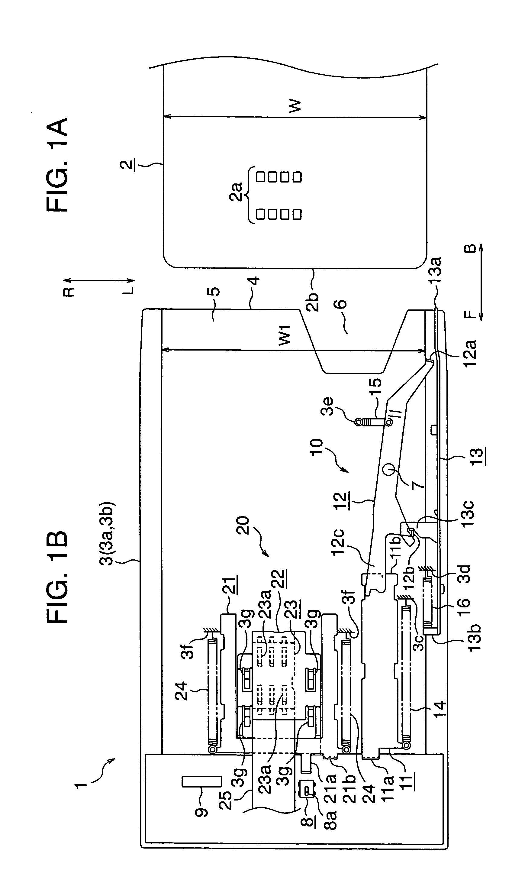
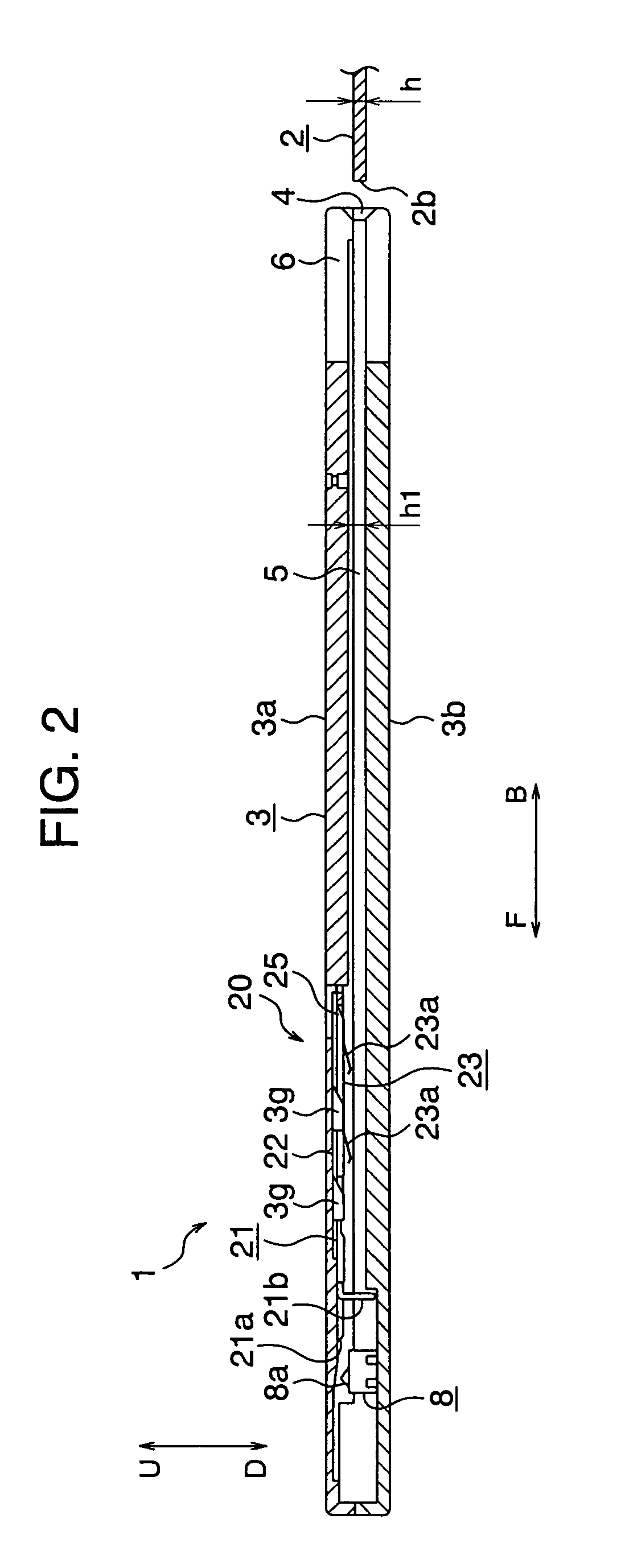
[0032]FIGS. 1A and 1B and FIG. 2 are diagrams showing the internal structure of an IC card reader related to an embodiment of the present invention. FIGS. 1A and 1B are the plan views of the same, and FIG. 2 is the lateral cross-sectional view of the same. In FIGS. 1A and 1B, reference numeral 1 designates the card reader. This card reader 1 performs read and write processing of information with respect to a contact-type IC card 2. IC card 2 is provided with IC contact points 2a on the front face and in its interior, it is provided with an IC chip (not shown) wherein prescribed data are stored. Reference 3 designates a frame of IC card reader 1. This frame 3 is assembled, as shown in FIG. 2, by superposing and combining an upper frame 3a and a lower frame 3b. In frame 3, there are formed an insertion slot 4 into which IC card 2 is inserted and a card insertion path 5. In the proximity of insertion slot 4, a notch 6 is provided. By inserting a finger in this notch 6, it is possible t...


PUM


Abstract

An IC card reader includes contactors contacting to IC contact points of the IC card, a frame forming with a card insertion path into which the IC card is inserted and a retraction domain for retracting the contactors in a direction away from the insertion path, a plate spring biasing the contactors to the retraction domain, and a mechanism responsive to the insertion of the IC card, advancing the contactors into the insertion path with the plate spring deflected to make contact the contactors to the IC contact points of the IC card, and responsive to extraction of the IC card and retracting the contactors to the retraction domain with the plate spring released force of the plate spring, becoming difficult for deformation and damage of the contactors.

Description

INCORPORATION BY REFERENCE[0001]The present application claims priority from Japanese application JP2004-075552 filed on Mar. 17, 2004, the content of which is hereby incorporated by reference into this application.BACKGROUND OF THE INVENTION[0002]The present invention pertains to an IC (Integrated Circuit) card reader which performs processing of information by bringing contactors into contact with IC contact points of the IC card.[0003]There are IC card readers which perform information processing with respect to contact-type IC cards. These IC card readers ensure a state of electrical connection with the IC card by bringing electrically conductive contactors into contact with IC contact points provided on the front face of the IC card, and, through the contact or and the IC contact, perform read or write processing of information with respect to the IC card.[0004]In order to bring contactors into contact with the IC contact points of an IC card, various structures have been propo...

Claims


Application Information

Patent Timeline
Patent Type & Authority Patents(United States)
IPC IPC(8): G06K13/00G06K7/00G06K7/06G06K17/00G06K13/08
CPCG06K7/0021G06K7/0026
Inventor ISHII, MASAYUKI
Owner HITACHI OMRON TERMINAL SOLUTIONS CORP
Why Eureka
Try Eureka