Flat acoustic conversion device

Inactive Publication Date: 2007-02-06
FPS
View PDF13 Cites 41 Cited by
  • Summary
  • Abstract
  • Description
  • Claims
  • Application Information

AI Technical Summary

Benefits of technology

[0023]As a result, the magnetic flux generated by each magnet travels from the first magnetic pole face to the second magnetic pole face or from the second magnetic pole face to the first magnetic pole face and the magnetic flux in the area between the first magnetic pole face and the second magnetic pole face, and accordingly, the magnetic flux in the area between the first magnet and the second magnet travels in a direction substantially parallel to the surface of the vibrating member. When the first magnet and second magnet are spaced a predetermined distance apart, the density of the magnetic flux in a direction parallel to the surface of the vibrating membrane in the area between the first magnet and second magnet decreases as the distance between the magnets increases. However, in the present invention, because the first magnet and second magnet are placed adjacent to or in contact with each other, the density of the magnetic flux in a direction parallel to the surface of the vibrating member can be set at the maximum enabling the sound pressure to be increased.
[0097]In addition, if the shape of at least one of the first and second magnets is made in a plurality of types, it is possible to arrange the first and second magnets to match the shape of the flat speaker. Therefore, the effect is obtained that the flat acoustic conversion device can have any shape allowing increased freedom when designing the shape of the overall speaker.

Problems solved by technology

The problem then arises that this force in a direction along the surface of the vibrating membrane causes twisting in the surface of the vibrating membrane and becomes a noise component in the acoustic signal leading to a reduction in the sound quality.
Therefore, the problem has been that, not only has it not been possible to obtain sufficient volume due the deterioration in the efficiency of the acoustic conversion, but the sound quality has also been low.
Furthermore, the shape of the speakers has been determined by the length and number of the bar magnets used, which has placed limitations on freedom of the speaker design.
Moreover, the problem has also existed that, because a coil is provided for each bar magnet along the longitudinal direction of the bar magnets, there has been a lack of flexibility in the setting of the speaker impedance to a suitable value.
Therefore, the further problem exists that, because the vibrating membrane is twisted due to the sound pressure distribution corresponding to this phase difference becoming a noise component in the acoustic signal, the sound quality is further deteriorated.
However, the vibration of the vibrating membrane is hindered by the pliable material so that the sound quality of low sounds in particular is deteriorated.
As a result, the efficiency of acoustic conversion is poor and a sufficient sound volume cannot be obtained, and in addition, sufficient sound quality cannot be obtained.
Further, the configuration of the speaker is determined by the length of the bar magnet and the number of bar magnets which are provided, such that the degrees in freedom in designing the configuration of the speaker are limited.
Thus, a problem arises in that there is little flexibility in setting the impedance of the speaker to an appropriate value.
Moreover, although, in conventional flat speakers, the vibrating membrane is placed adjacent to the magnetic pole face of the bar magnets, a gap exists between the vibrating membrane and the magnetic pole face.
Therefore, the problem exists that the flat speaker itself is made too thick.
Furthermore, if the shape of a conventional flat speaker is made still larger and narrower, slackness develops in the vibrating membrane leading to the vibrating membrane and the yoke no longer being parallel to each other.
Consequently, the distances from each point on the vibrating membrane to the yoke or the magnetic pole face of the bar magnets is not uniform.
The result of this is that the drawback arises that a phase difference is generated in the reflected sound which is reflected by the yoke and the like so as to come back to the vibrating membrane, and twisting of the vibrating membrane is caused by the sound pressure distribution.

Method used


Image

  • Flat acoustic conversion device
  • Flat acoustic conversion device
  • Flat acoustic conversion device

Examples


first embodiment

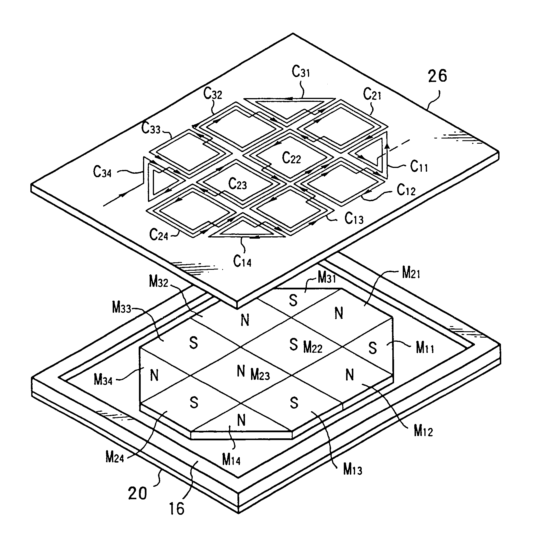
[0147]As is shown in FIG. 9, the flat speaker unit of the first embodiment is provided with a yoke 20 comprising a rectangular plate-shaped member formed from a magnetic body. A flat, triangular permanent magnet M11 is disposed at one corner portion of the top surface of the yoke 20 with the S polarity magnetic pole face thereof facing upwards and with the oblique line of the triangle facing towards the corner of the yoke 20. The permanent magnet M11 is fixed in place using an adhesive. A ferrite based magnet or neodymium based magnet can be used for the permanent magnet.

[0148]A flat, quadrangular permanent magnet M12 is disposed at a position adjacent to the permanent magnet M11 along the longitudinal side of the yoke 20 with the N polarity magnetic pole face thereof facing upwards and with the surface of one side thereof in contact with the surface of one side of the permanent magnet M11.

[0149]A flat, quadrangular permanent magnet M13 is disposed at a position adjacent to the perm...

second embodiment

[0164]The second embodiment of the present invention will now be described with reference made to FIG. 11. The acoustic conversion device according to the second embodiment is formed from a magnetic material and is provided with a yoke 20 comprising a rectangular plate-shaped member in the outer peripheral portions of which are punched a plurality of holes 20A. Magnet fixing portions to which are fixed permanent magnets are formed in the area of the yoke 20 surrounded by the holes 20A.

[0165]Flat, quadrangular permanent magnets m11 to m38 are fixed to the magnet fixing portions with an adhesive with the side surfaces of each magnet in contact with the adjacent permanent magnets with no gaps between each magnet such that the upward facing magnetic pole faces of adjacent permanent magnets have alternating polarities. Namely, permanent magnets mij (wherein when i=1 or 3, then j=1, 3, 5, or 7 and when i=2, then j=2, 4, 6, or 8) are fixed in place such that S polarity magnetic pole faces ...

third embodiment

[0188]The third embodiment of the present invention will now be described with reference made to FIGS. 17 and 18. As is shown in FIGS. 17 and 18, the acoustic conversion device according to the third embodiment is formed from a magnetic material and is provided with a yoke 20 comprising a rectangular plate-shaped member in the outer peripheral portions of which are punched a plurality of holes 20A. Magnet fixing portions to which are fixed permanent magnets are formed in the area of the yoke 20 surrounded by the holes 20A. Small boss insertion holes 20B for inserting bosses formed in a case are punched in the four corners of the yoke 20.

[0189]One of a plurality of flat, quadrangular permanent magnets m is fixed to each of the magnet fixing portions with an adhesive with the magnet side surfaces in contact with the adjacent permanent magnets with no gaps between each magnet such that the upward facing magnetic pole faces of adjacent permanent magnets have alternating polarities. Name...


PUM


Abstract

A flat acoustic conversion device includes two magnets disposed so that their magnetic poles face upward arid are adjacent to or in contact with one another, and the magnetic pole faces of different polarities arc disposed alternately; a vibrating member disposed on the top surface of the yoke; coil pairs wound in helical form and disposed at front and reverse surfaces of the vibrating membrane; such that magnetic flux traveling in a direction substantially parallel to a surface of the vibrating membrane becomes a maximum, and interlinks with the coil pairs. When current is supplied to the coils, a direction of force which the current receives from a magnetic field is substantially orthogonal to the surface of the vibrating membrane, and force in a direction along the surface of the vibrating membrane becomes extremely low. Thus, noise components can be reduced such that sound quality can be improved.

Description

BACKGROUND OF THE INVENTION[0001]1. Field of the Invention[0002]The present invention relates to a flat acoustic conversion device, and particularly to a flat acoustic conversion device such as a flat speaker which can be used as a flat speaker, a flat microphone, and a microphone.[0003]2. Description of the Related Art[0004]FIG. 1 is a diagram showing the basic structure of a conventional flat speaker. This flat speaker is provided with a plurality of bar magnets 1 which are arranged in parallel on a yoke 4, a vibrating membrane 2 disposed parallel and adjacent to a magnetic pole face of the bar magnets 1, and a plurality of coils 3 each formed at a position on the vibrating membrane which corresponds to the magnetic pole face of the bar magnets in such a manner that the electric current flows in a direction orthogonal to the magnetic field generated by the bar magnets 1. Each coil 3 is disposed at a position where the greater part of the inner periphery of each coil faces the magn...

Claims


Application Information

Patent Timeline
IPC IPC(8): H04R25/00H04R7/04H04R9/02H04R9/04
CPCH04R7/04H04R9/047H04R9/046H04R9/025H04R9/00
Inventor SUZUKI, TAKAHISAHORI, MASASHIOHBAYASHI, KUNIHIKO
Owner FPS
Why Eureka
Try Eureka