Pointer instrument

a pointer and instrument technology, applied in the field of pointers, can solve the problems of further disadvantages in the movement path region of the pointer, and add structural space restrictions, and achieve the effect of partial flexibility

Inactive Publication Date: 2008-05-13
CONTINENTAL AUTOMOTIVE GMBH
View PDF29 Cites 9 Cited by
  • Summary
  • Abstract
  • Description
  • Claims
  • Application Information

AI Technical Summary

Benefits of technology

[0008]The particular advantage of the invention resides in the elimination of the need for a power supply for a light source arranged on the pointer. The invention's guiding of light from a stationary light source to the moving pointer with the interposition of an interface of the optical waveguide element and an interface of the carrier body or pointer allows the use of existing light sources for illuminating a moving pointer. In this way, it is possible to omit the flexible conductor that entails structural restrictions and to omit a light source arranged on the pointer. The resulting free space can be used for further indication modules. A particularly advantageous application of the invention is in the case of a design of the pointer or carrier body as a ring pointer or ring which is mounted and driven at locations on its circumference and in this way leaves the central region free. The carrier body which carries the pointer may expediently be covered toward the observer, so that only the pointer is visible.
[0009]An optical waveguide element may advantageously be arranged on that side of the carrier body which is remote from an observer, which optical waveguide element has a first coupling-in area, into which light from at least one light source can be introduced, and which optical waveguide element has a first coupling-out area extending along the movement path of the pointer. The pointer and / or the carrier body has a second coupling-in area, which is arranged opposite the first coupling-out area of the optical waveguide element, so that light emerging from the first coupling-out area can enter into the second coupling-in area of the pointer and / or of the carrier body. The pointer is formed such that it can be illuminated in this way. This configuration solves the problem of guiding light to the moving pointer particularly expediently by virtue of pairs of coupling-in areas—coupling-out areas of the pointer and the optical waveguide being configured such that they are relatively movable with respect to one another.
[0010]The pointer instrument may have a scale extending along the movement path of the pointer, so that the pointer is formed such that it can be moved along the scale in order to indicate measured values. Particularly in the case of a curved or even circle-segment-shaped movement path of the pointer, it is expedient for a traditionally appealing appearance if the pointer on the radially inner side of the scale indicates the measured values in an outwardly directed manner. In order to attain a larger free region radially on the inside of the movement path, the pointer may also expediently indicate the measured values radially from the outside.
[0011]Particular flexibility is attained by representing the scale on a display. In this way, e.g. a changeover of the physical unit of the scaling can be effected without any problems.
[0012]In accordance with the arrangement and the pointing direction of the pointer—that is to say radially outwardly or radially inwardly—it is expedient to arrange the scale radially outside the circle or radially inside.
[0013]The present invention is particularly suitable in conjunction with light sources formed as light emitting diodes, since, on account of their low evolution of heat, these can also be arranged close to the first coupling-in area in an unproblematic manner. In this case, it is expedient, particularly when using surface mounted (SMD) light emitting diodes, for the optical waveguide element to be arranged directly on a printed circuit board and to be fixed there. A design of the optical waveguide element which has a plurality of coupling-in areas, at each of which at least one light source or light emitting diode is provided, is particularly advantageous in this case. The coupling-in areas may in this case be provided as end cutouts in the optical waveguide element. The light sources or light emitting diodes may also be formed such that they emit light of different colors along the movement path of the pointer or can even be changed over with regard to the light emission color. A particularly expedient configuration of the optical waveguide element is one which provides at least in part an embodiment of the direction of extent parallel to the indication at least in sections as a preferably circle-segment-shaped ring whose first end side is provided with at least one first coupling-in area and whose second end side is provided with at least one first coupling-out area.

Problems solved by technology

Furthermore, the structural depth of the carrier body is increased at least in sections on account of the required precautions for the active illumination, so that structural space restrictions in the region of the movement path of the pointer are added as a further disadvantage.

Method used


Image

  • Pointer instrument
  • Pointer instrument
  • Pointer instrument

Examples


Embodiment Construction

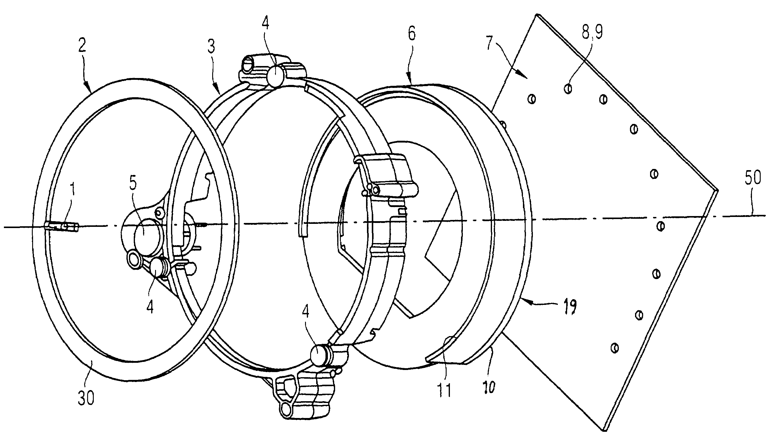
[0023]FIG. 1 shows essential components of a pointer instrument according to the present invention which are arranged along an axis 50 of rotation. The pointer instrument includes a pointer 1 with a carrier body 2, a holder 3 with three bearings 4 and a pointer drive 5, an optical waveguide element 6, a printed circuit board 7 and light sources 9 formed as light emitting diodes 8, which are fixed and electrically contact-connected as SMD on the printed circuit board 7.

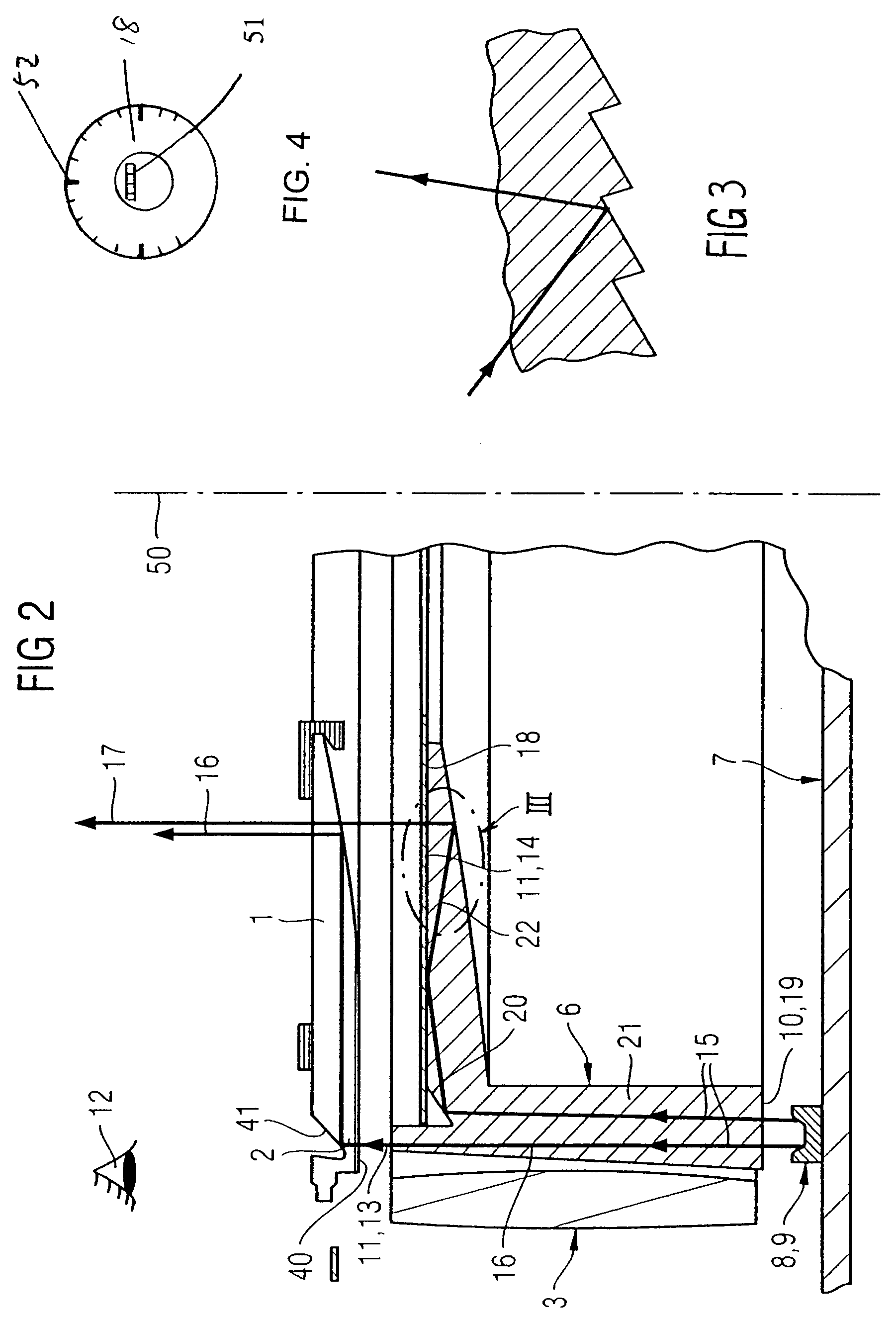
[0024]The optical waveguide element 6 is essentially formed as a cylindrical ring, a first end side 10 being provided with first coupling-in areas 19 illustrated in FIG. 1 and being arranged on the printed circuit board 7. The light emitting diodes8 are arranged on the printed circuit board 7 at essentially equidistant distances from one another in a manner following the ring form, and radiating into the first coupling-in areas 19. FIG. 2 shows light from one of the light emitting diodes 8 entering one of the first cou...


PUM


Abstract

A pointer instrument for a motor vehicle includes a pointer drive for deflecting a carrier body. A pointer which is visible in an indication is provided on the carrier body. An optical waveguide element is arranged on that side of the carrier body which is remote from an observer. Light from at least one light source is introduced into the optical waveguide element which extends along the movement path of the pointer. Light emerging from the optical waveguide element enters into the pointer and / or the carrier body, and the pointer is formed such that it is illuminated by light emerging from the optical waveguide element.

Description

CROSS-REFERENCE TO RELATED APPLICATIONS[0001]The present application claims priority to U.S. Provisional Patent Application No. 60 / 696,705, filed Jul. 5, 2005, the entire contents of which are incorporated herein by reference. The present application also claims priority to DE 10 2004 060 693, filed Dec. 16, 2004.BACKGROUND OF THE INVENTION[0002]The invention relates to a pointer instrument, in particular for a motor vehicle, having a pointer drive for the deflection of a carrier body which can be rotated about an axis of rotation and on which is provided a pointer which is visible in an indication and is mounted outside the axis of rotation.[0003]In pointer instruments of this type, the pointer is typically illuminated to ensure a problem-free reading even with diminishing light at twilight or at night. The arrangement of the pointer at a carrier body furthermore affords the advantage of being able to configure the carrier body in the form of a ring, for example, and in this way, g...

Claims


Application Information

Patent Timeline
Patent Type & Authority Patents(United States)
IPC IPC(8): G01D11/28G12B11/04
CPCG01D11/28G01D13/265Y10S116/36B60K2370/6992
Inventor BALSFULLAND, WOLFGANGFRIEPES, GERHARDFORSTER, AXELHURTH, PATRIK
Owner CONTINENTAL AUTOMOTIVE GMBH
Why Eureka
Try Eureka