
System and methodology for asynchronous code refactoring with symbol injection

a technology of asynchronous code and symbol injection, applied in the field of system and methodology for asynchronous code refactoring with symbol injection, can solve the problems of initial design loss, unnecessary complexity in the software application, and the development and use of such applications

Inactive Publication Date: 2008-05-06
BORLAND
View PDF21 Cites 69 Cited by
  • Summary
  • Abstract
  • Description
  • Claims
  • Application Information

AI Technical Summary

Benefits of technology

[0025]A system and methodology for asynchronous code refactoring with symbol injection is described. In one embodiment, for example, a method of the present invention is described for refactoring a plurality of interdependent software modules that reside in separate projects, the method comprises steps of: in response to a change that affects a particular symbol of a software module that resides in a first project, refactoring the software module of the first project to propagate

Problems solved by technology

Although integrated development environments facilitate the development of applications, issues remain in the development and use of such applications.
One problem is that when a large software program or application evolves over time it is common that the initial design gets lost as features that were not in the original specification are added to the application.
However, this will often lead to unnecessary complexity in the software application, as it is unknown beforehand which parts of the application will require this additional flexibility.
Refactoring of a system may be small or extensive, but even small changes can introduce errors or “defects” into the system.
A particular problem in refactoring a complex application or system is that the application or system may be made up of a number of different modules that are separately developed.
A particular concern is, therefore, that the changes made during the refactoring might “break” the system, because the change is incompatible with other, dependent modules of the system.
A common problem in the lifecycle of a software system is the ability to change application programming interfaces (APIs) in libraries.
Any change of the API in a library which may result from changing source(s) of the library may result in errors in the parsing / attribution of the clients of this library (hereinafter “dependents”).
This may limit or prevent the execution of traditional refactorings for the library.
Accordingly, if the library is refactored, the dependent applications will be out of sync with the library and compilation errors may occur when they attempt to use the library.
When these components are integrated into a system they need to work with each other and changes made to one component may impact other components of the system.
Disadvantages of this approach include that this manual refactoring solution is both tedious and error prone.
He or she might miss some of the errors or may otherwise introduce incorrect behavior.
In some cases the application may compile, even though underlying errors remain that were not addressed.
Another problem is the possibility that new errors may be introduced during the manual fix-up process.
However, this approach also adds considerable complexity to the library and may serve to make the refactoring impractical in many cases.
Disadvantages of these approaches of supporting multiple interfaces or to retrofitting support for old versions into the newly refactored library include that they will cause the library to become more complex and, therefore, may also make it more fragile and susceptible to error.
Use of either of these approaches also makes the library more difficult to design and implement and may take away many of the advantages of refactoring the library in the first place.
This avoids the above-described compatibility problems, but has the disadvantage of limiting the ability to implement needed changes.

Method used


Image

  • System and methodology for asynchronous code refactoring with symbol injection
  • System and methodology for asynchronous code refactoring with symbol injection
  • System and methodology for asynchronous code refactoring with symbol injection

Examples


Embodiment Construction

[0038]Glossary

[0039]The following definitions are offered for purposes of illustration, not limitation, in order to assist with understanding the discussion that follows.

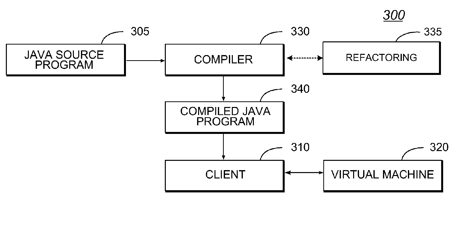
[0040]Bytecode: A virtual machine executes virtual machine low-level code instructions called bytecodes. Both the Sun Microsystems Java® virtual machine and the Microsoft .NET virtual machine provide a compiler to transform the respective source program (i.e., a Java® program or a C# program, respectively) into virtual machine bytecodes.

[0041]Compiler: A compiler is a program which translates source code into binary code to be executed by a computer. The compiler derives its name from the way it works, looking at the entire piece of source code and collecting and reorganizing the instructions. Thus, a compiler differs from an interpreter which analyzes and executes each line of code in succession, without looking at the entire program. A “Java compiler” translates source code written in the Java® programming languag...


PUM


Abstract

A system and methodology for asynchronous code refactoring with symbol injection is described. In one embodiment, for example, a method is described for refactoring a plurality of interdependent software modules that reside in separate projects, the method comprises steps of: in response to a change that affects a particular symbol of a software module that resides in a first project, refactoring the software module of the first project to propagate the change to all instances of the particular symbol in the software module; during the refactoring of the software module of the first project, recording meta data about the refactoring that is required to effect the change; and automatically propagating the change to a dependent software module residing in a second project, by refactoring the dependent software module based on the recorded meta data about the refactoring that occurred to the software module of the first project.

Description

CROSS REFERENCE TO RELATED APPLICATIONS[0001]The present application is related to the following commonly-owned, presently-pending application(s): application Ser. No. 10 / 209,283, filed Jul. 30, 2002, entitled “System and Methodology Providing Compiler-Assisted Refactoring”. The disclosure of the foregoing application is hereby incorporated by reference in its entirety, including any appendices or attachments thereof, for all purposes.COPYRIGHT STATEMENT[0002]A portion of the disclosure of this patent document contains material which is subject to copyright protection. The copyright owner has no objection to the facsimile reproduction by anyone of the patent document or the patent disclosure as it appears in the Patent and Trademark Office patent file or records, but otherwise reserves all copyright rights whatsoever.APPENDIX DATA[0003]Computer Program Listing Appendix under Sec. 1.52(e): This application includes a transmittal under 37 C.F.R. Sec. 1.52(e) of a Computer Program List...

Claims


Application Information

Patent Timeline
IPC IPC(8): G06F9/44
CPCG06F8/4441G06F8/72G06F8/427G06F8/436
Inventor HOWE, MARK K.LITCHEV, LUBOMIR B.KEMPER, CHRISTIAN K.
Owner BORLAND
Learn More