
Probe head having a membrane suspended probe

a probe head and probe technology, applied in the field of probe assemblies, can solve the problems of affecting the accuracy of the probe head,

Active Publication Date: 2008-05-06
FORMFACTOR INC
View PDF987 Cites 73 Cited by
  • Summary
  • Abstract
  • Description
  • Claims
  • Application Information

AI Technical Summary

Benefits of technology

The patent text describes two types of probing assemblies used for testing integrated circuits. The first type uses needle-like probes with a limited pitch between the probes, which may not be suitable for high-frequency devices. The second type uses a membrane probing assembly with a more flexible probe card and a space transformer for re-routing signals. The technical effect of the patent text is to provide a probing assembly that can accommodate finely pitched contact pads on the integrated circuit with low inductance, low compliance, and low damage to the probes, allowing for accurate measurements and reliable testing of high-frequency devices.

Problems solved by technology

Needle card probing assemblies have been used extensively in wafer testing, but the trend in electronic production, and, in particular, IC production, to higher frequency, more complex circuits having smaller circuit elements and geometries has exposed several limitations of this type of probing device.
First, the pitch, the distance between the probes, is limited by manufacturing tolerances and assembly considerations to about 125 □m, a spacing greater than desirable for many ICs having finely pitched contact pads.
This causes rapid dulling of the pointed probe ends, frequent bending or breaking of the probes, and may damage the contact pad if penetration is too great.
The contact pad material also adheres to the probe and frequent cleaning is required which often damages the probes.
Typically, the relatively long, closely spaced, needle-like probes exhibit a single path inductance of 1-2 nH which is sufficient to substantially distort high frequency signals, limiting the usefulness of needle-type probes for testing high frequency devices.
Heretofore, membrane suspended probes have not been adaptable for use with the probe cards and space transformers suitable for use with a needle card-type probe heads where the signal paths pass through the center of the probing assembly and are arranged substantially parallel to the central axis of the probing assembly.

Method used


Image

  • Probe head having a membrane suspended probe
  • Probe head having a membrane suspended probe
  • Probe head having a membrane suspended probe

Examples


Embodiment Construction

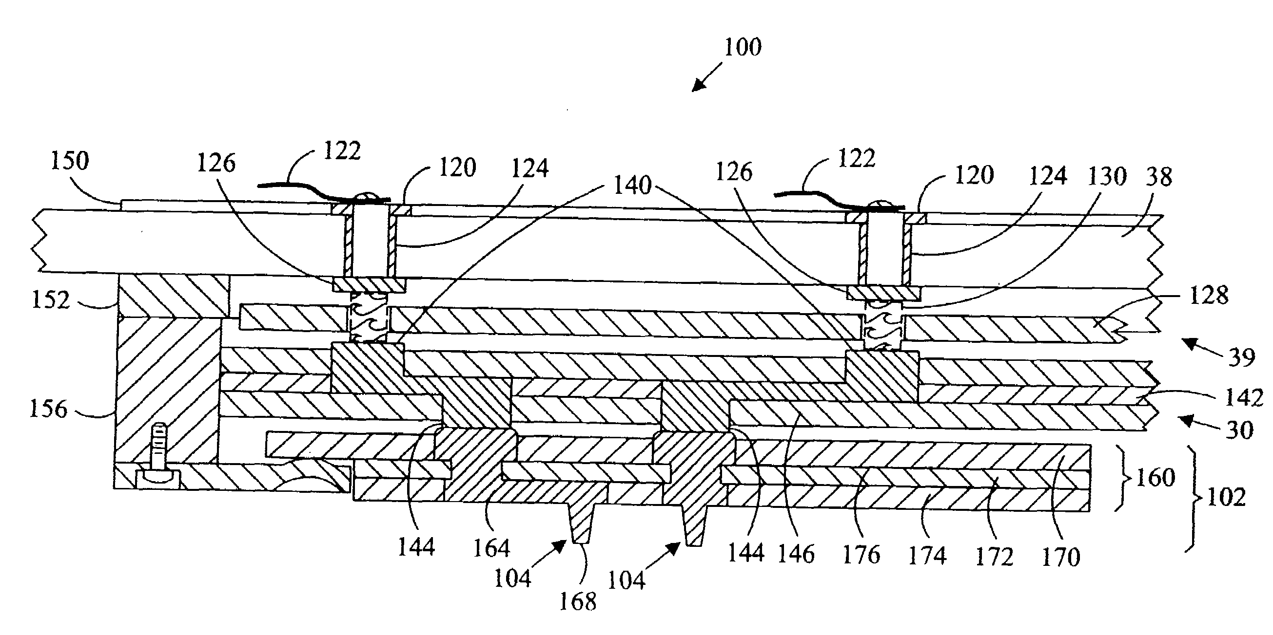
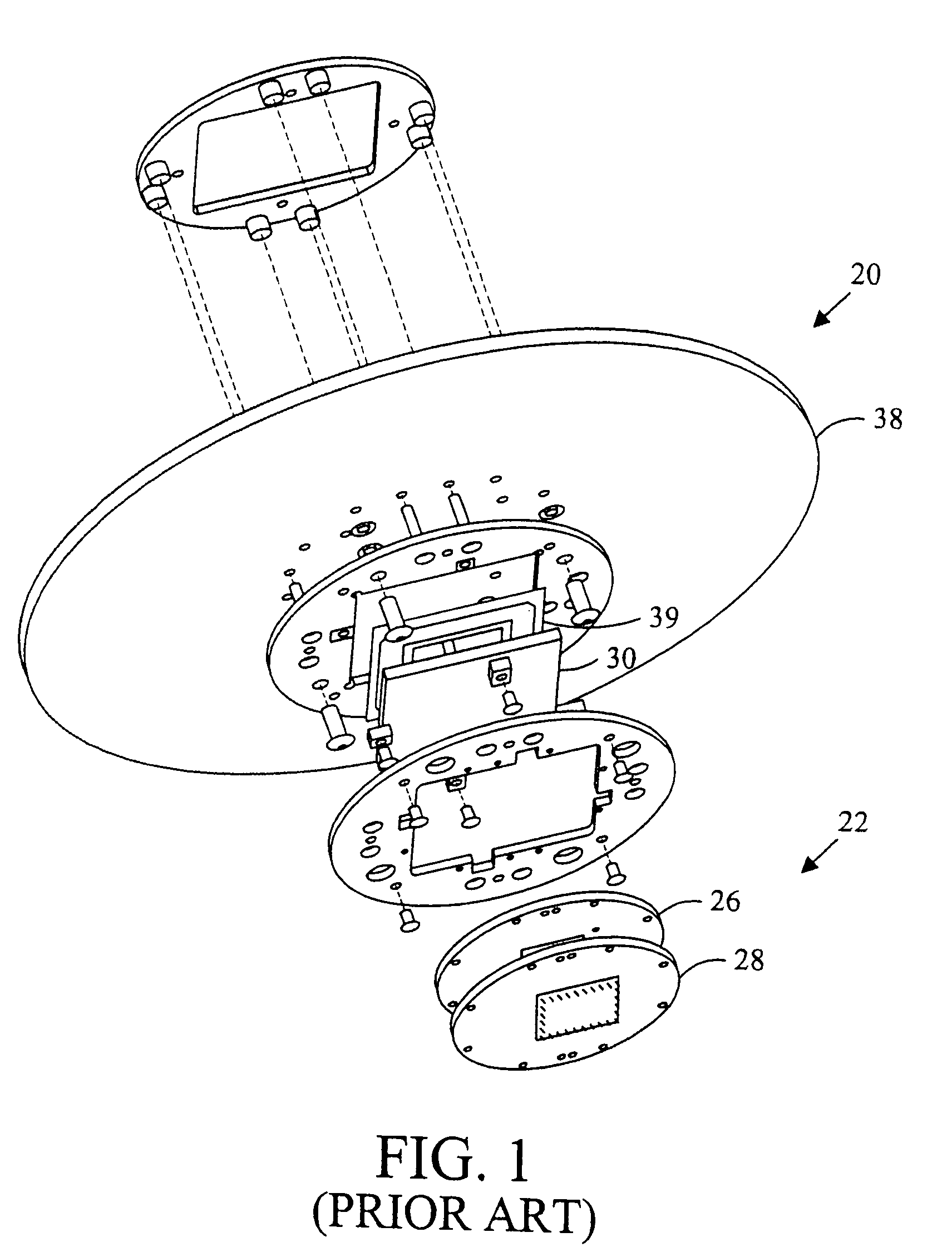
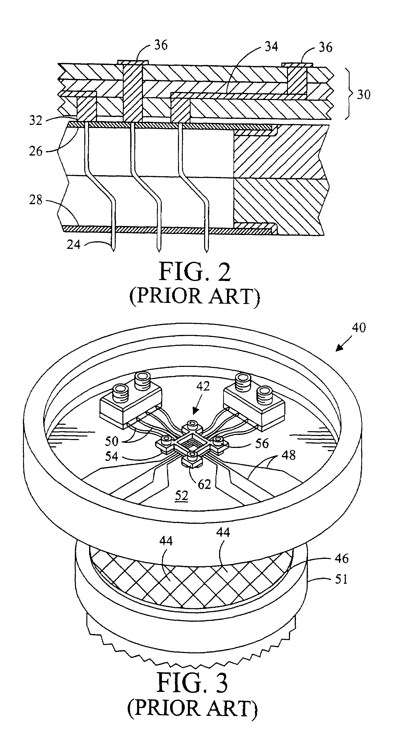
[0032]Referring in detail to the drawings where similar parts of the invention are identified by like reference numerals, and, more particularly, to FIG. 1, an embodiment of a probing assembly 20 suitable for use with needle-type probes includes as its major functional components a probe card 38, an interposer 39, a space transformer 30, and a probe head 22. Referring also to FIG. 2, needle-like probes 24 in the probe head provide a means of making temporary interconnections to contact pads on a die included on a semiconductor wafer or other device under test (DUT) and conducting signals to and from the integrated electrical circuit on the DUT. The needle-like probes conduct the signals to and from the die through the probe head 22 to conductive terminals 32 or pads on the space transformer 30. The signal paths of the needle card-type probing assembly are typically grouped around the center of the probing assembly and substantially normal to the device under test. While needle probe...


PUM


Abstract

A probe head including an elastic membrane capable of exerting a restoring force when one of the surfaces of the elastic membrane is distorted. A conductive probe includes a beam having a first end and a second end, with a probe tip proximate the first end for contacting a device under test. A beam contact proximate the second end of the beam. The beam being movable to deform at least one surface of the elastic membrane.

Description

CROSS-REFERENCE TO RELATED APPLICATIONS[0001]This application claims the benefit of U.S. Provisional Patent Application No. 60 / 586,299 entitled “Probe Head Having a Membrane Suspended Probe,” invented by Kenneth Smith, Michael Jolley and Victoria Van Sycle on Jul. 7, 2004.BACKGROUND OF THE INVENTION[0002]The present invention relates to probing assemblies of the type commonly used for testing integrated circuits (ICs) and, in particular, to a probing assembly providing finely pitched, compliant probes having very low inductance.[0003]Integrated circuit technology permits fabrication of a number of discrete electronic circuit elements on a single substrate or “wafer.” After fabrication, this wafer is divided into a number of rectangular-shaped chips or dies where each die includes a rectangular or other regular arrangement of metallized contact pads or bond pads through which input and output connections can be made to the electronic circuit on the die. Although each die is eventuall...

Claims


Application Information

Patent Timeline
Patent Type & Authority Patents(United States)
IPC IPC(8): G01R31/02
CPCG01R1/0735G01R1/07371G01R1/067G01R31/26H01L22/00B82Y15/00
Inventor SMITH, KENNETHJOLLEY, MICHAELVAN SYCKEL, VICTORIA
Owner FORMFACTOR INC
Learn More