Eureka AIR delivers breakthrough ideas for toughest innovation challenges, trusted by R&D personnel around the world.

Agitation tank for storing beer yeast slurry

a technology for agitation tanks and yeast slurry, which is applied in the direction of alcoholic beverage preparation, rotary stirring mixers, and after-treatment of biomass, etc. it can solve the problems of unfavorable uniform mixing of the entire yeast slurry through low-speed stirring, unfavorable uniform mixing of the whole yeast slurry, and damage to yeast, so as to prevent damage to yeast.

Inactive Publication Date: 2008-05-06
ASAHI BREWERIES LTD
View PDF26 Cites 6 Cited by
  • Summary
  • Abstract
  • Description
  • Claims
  • Application Information

AI Technical Summary

Benefits of technology

[0009]The present invention has been conceived to solve the above contradictory problems. It is an object of the present invention to stir and mix the entire yeast slurry within the stirred tank in a short period of time without causing poor mixing of the yeast slurry or a non-Newtonian fluid, as well as protect yeast from damages and hence prevent the deterioration of the biological activity.
[0014]By those of the present invention, the yeast slurry within the stirred tank can be entirely and substantially uniformly mixed, so that the mixing and stirring effect can be remarkably enhanced as compared with a yeast stirred tank provided with a conventional inclined paddle impeller or the like.
[0015]Since the stirring impeller is so constructed that a maximum diameter of the rotation body defined by the rotation of the stirring impeller is 60-90% of the inner diameter of the stirred tank and the height of the rotation body is 70% or more of a standard depth of the yeast slurry normally stored in the stirred tank, a desirable stirring effect can be produced even through a relatively low rotational speed stirring at 1-30 rpm. As a result, there is produced an effect that the stirring is unlikely to damage and destroy yeast, and hence deteriorate its biological activity.
[0017]With the rotation body having a maximum diameter of 70-90% of the inner diameter of the stirred tank, it is possible to more securely prevent the yeast slurry from stagnating in proximity to the inner wall of the stirred tank, thereby enabling the yeast slurry to be more uniformly stirred.
[0020]With the rotation body having a height of 90-120% of the standard depth of the yeast slurry, it is possible to more uniformly stir and mix the yeast slurry and produce an effect to instantly eliminate foaming of yeast slurry generated as it is filled into the stirred tank.
[0023]With the stirring impeller rotated at 1-20 rpm, there is produced an effect of more securely preventing damages of yeast due to shearing force.

Problems solved by technology

Yeast stored in the stirred tank settles down on a bottom of the stirred tank as the time lapses, resulting in non-uniform yeast concentration in the stirred tank or non-uniform temperature when cooled.
However, in case that yeast slurry which is a non-Newtonian fluid is stirred by using such a conventional stirring impeller, there arises a problem that uniformly mixing of the entire yeast slurry is unlikely to be achieved through low-speed stirring.
On the other hand, there arises another problem in high-speed and strong stirring which is performed for improved uniformity in the yeast concentration and temperature of the yeast slurry, that yeast may be damaged and destroyed, and hence its biological activity may be lowered.

Method used


Image

  • Agitation tank for storing beer yeast slurry
  • Agitation tank for storing beer yeast slurry
  • Agitation tank for storing beer yeast slurry

Examples


embodiment 1

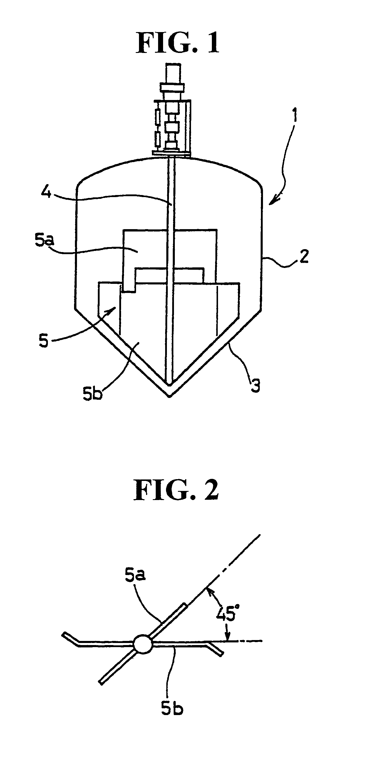
[0041]As illustrated in FIG. 1, the stirred tank has a tank body 1 with a shell portion 2 having a substantially cylindrical shape and bottom portion 3 having an inverted cone shape.

[0042]Rotational shaft 4 extends substantially through the center of the tank body 1 and has upper part and lower part to which paddle blades 5a, 5b are respectively mounted at a perpendicular orientation.

[0043]The upper paddle blades 5a intersect the lower paddle blades 5b at an angle of 45 degrees, as illustrated in FIG. 2.

[0044]The stirring impeller 5 made up of both paddle blades 5a, 5b is set so that a maximum diameter of a rotation body defined by the rotation of the stirring impeller 5 is 60-90% of the inner diameter of the stirred tank.

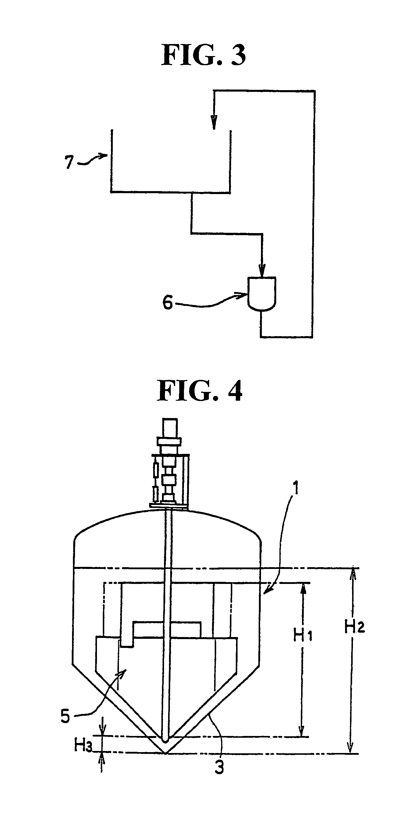
[0045]The height of the rotation body defined by the rotation of the stirring impeller 5 is set to be 70% or more of a standard depth of yeast slurry normally stored in the stirred tank.

[0046]The lower paddle blades 5b have lower sides each having a slanting surfac...

example 1

[0086]In this example, the testing was conducted to determine the relationship between the stirring time and the variation in pH of the yeast slurry.

[0087]The stirred tank used in this example has a volume of 4 m3, an inner diameter of 1900 mm, and a stirring impeller having a maximum diameter of 60% of the inner diameter of the stirred tank.

[0088]The stirring impeller was so constructed that the rotation body defined by the rotation of the stirring impeller has a height of 1490 mm. As a result, the height of the rotation body is 97% of the standard depth of the yeast slurry, and the upper edges of the stirring impeller are about 50 mm above the top surface of the yeast slurry having the standard depth.

[0089]The stirring impeller also has the upper and lower paddles 5a, 5b disposed along the vertical axis and intersecting each other at an angle of 45 degrees.

[0090]In this embodiment, the stirring was performed at a low speed of 20 rpm.

[0091]On the other hand, an inclined paddle impe...

example 2

[0099]In this example, the measurement of the variation in yeast concentration at the time of discharging the yeast slurry was conducted.

[0100]The stirred tank used in this example has a volume of 5 m3 and an inner diameter of 2200 mm.

[0101]The stirring impeller was so constructed that the rotation body defined by the rotation of the rotational shaft has a maximum diameter of about 83% of the inner diameter of the stirred tank.

[0102]The stirring impeller was also so constructed that the rotation body defined by the rotation of the stirring impeller has a height of 1993 mm. As a result, the height of the rotation body is 93% of the standard depth of the yeast slurry, and the upper edges of the stirring impeller are about 50 mm above the top surface of the yeast slurry having the standard depth.

[0103]In this example, the stirring was performed at a rotation speed of 20 rpm (example 2-1) and 5 rpm (example 2-2), respectively.

[0104]On the other hand, a stirred tank provided with a prope...


PUM

PropertyMeasurementUnit
angleaaaaaaaaaa
intersecting angleaaaaaaaaaa

Abstract

According to the present invention, there is provided a stirred tank for storing yeast slurry to be supplied to fermentation tanks where fermented foods such as beer are fermented, is characterized in that a stirring impeller is provided within the stirred tank and so constructed that a maximum diameter of a rotation body defined by the rotation of the stirring impeller is 60-90% of the inner diameter of the stirred tank, and the height of the rotation body is 70% or more of a standard depth of the yeast slurry normally stored in the stirred tank.

Description

FIELD OF THE INVENTION[0001]This invention relates to a stirred tank for storing yeast slurry, method of manufacturing fermented foods using the stirred tank, and a stirring impeller provided in the stirred tank. The present invention is applied particularly in a beer manufacturing process.BACKGROUND OF THE INVENTION[0002]Commonly, in the process of manufacturing fermented products such as beer, yeast recovered from a fermentation tank is stored in the stirred tank, and then returned as seed yeast to the fermentation tank for reuse.[0003]Yeast stored in the stirred tank settles down on a bottom of the stirred tank as the time lapses, resulting in non-uniform yeast concentration in the stirred tank or non-uniform temperature when cooled. Hence, there arises a necessity to stir yeast slurry for overcoming such non-uniformity.[0004]However, likewise butter, soap, etc., the yeast slurry is a non-Newtonian fluid. It is known that in such non-Newtonian fluid, stirring effect in proportion...

Claims


Application Information

Patent Timeline
Patent Type & Authority Patents(United States)
IPC IPC(8): B01F7/04B01F7/18C12M1/02C12M1/10C12C11/02C12C13/00
CPCC12C11/003C12C11/02C12C13/00
Inventor ITO, HISAYOSHIOKAMOTO, YUKIMICHIKAWAMURA, KIMITOJIMBO, EIICHI
Owner ASAHI BREWERIES LTD
Why Eureka
Eureka Blog
Learn More