
Wideband enhanced digital injection predistortion system and method

a wideband enhanced, digital injection technology, applied in the direction of digital transmission, amplifier modification to reduce non-linear distortion, baseband system details, etc., can solve the problems of interference to communications in adjacent channels, modulations generating distortion components at the output of transmitters, and high undesirable interference of adjacent channels

Active Publication Date: 2008-04-29
INTEL CORP
View PDF51 Cites 23 Cited by
  • Summary
  • Abstract
  • Description
  • Claims
  • Application Information

AI Technical Summary

Benefits of technology

[0021]Further features and advantages of the present invention are set out in the following detailed description.

Problems solved by technology

Variations in the envelope magnitude of digital modulations generate distortion components at the output of the transmitter that are caused by the inherent nonlinearity of RF amplification circuits.
Amplifier distortion produces a dilation of the spectrum of the input signal (“spectral regrowth”) which causes interference to communications in adjacent channels.
Adjacent channel interference (ACI) is a highly undesirable phenomenon that is tightly controlled by regulatory organizations (FCC, ETSI, ITU).
In addition to spectral regrowth, amplifier nonlinearities produce in-band distortion (i.e. distortion components within the bandwidth of the modulated input signal) which deteriorates the integrity of the transmitted signal and results in high Bit Error Rate (BER) at the receiver end.
The price to pay for such a mild nonlinear behavior is poor efficiency, i.e. limited DC-to-RF power conversion performance.
Unfortunately it also produces a severe loss in efficiency due to reductions in RF output power resulting from higher OBO levels.
High efficiency amplifiers on the other hand cannot typically be linearized by simply increasing OBO and require more sophisticated linearization techniques.
Feedback linearization can be effective for narrow signal bandwidths but has very limited distortion correction capabilities when wide bandwidth operation is required (e.g. multicarrier WCDMA) due to input-output stability restrictions associated to loop dynamics.
Therefore, feedback would not be sufficient to linearize wide bandwidth, highly efficient transmitters.
However, and despite having wide bandwidth distortion correction capabilities, feed forward systems usually have low efficiency due to the DC power consumption of the error amplifier and the presence of lossy delay elements at the output of the main amplifier required for phase alignment of the distortion cancellation loop.
These “static” predistorters are not well suited for high efficiency base station transmitter designs due to the fact that nonlinear dynamic distortion components or “memory effects” constitute a substantial portion of the total output distortion of high power, high efficiency amplifiers.
The main disadvantages are large memory requirements for storing the predistortion coefficients and the computational complexity involved in the interpolation of table entries when there is unreliable / insufficient data for system adaptation.
Multitable interpolation complexity can be quite substantial, posing a limit to the accuracy and adaptation rate of the predistorter.
The accuracy of digital LUT predistorters is also limited by table quantization errors.
Quantization errors can severely limit distortion correction in high efficiency, high power transmitters in which wideband dynamic distortion compensation is necessary to meet stringent emissions specifications.
Unfortunately increasing the number of table entries in multitable designs is prohibitive due to the rapid increase in memory and computational requirements.
However, none of these approaches adequately addresses the above problems.

Method used


Image

  • Wideband enhanced digital injection predistortion system and method
  • Wideband enhanced digital injection predistortion system and method
  • Wideband enhanced digital injection predistortion system and method

Examples


Embodiment Construction

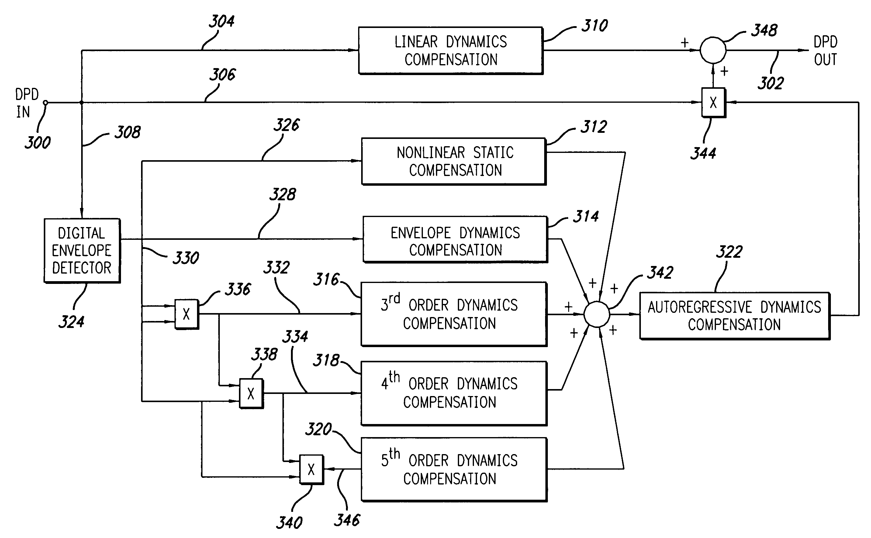
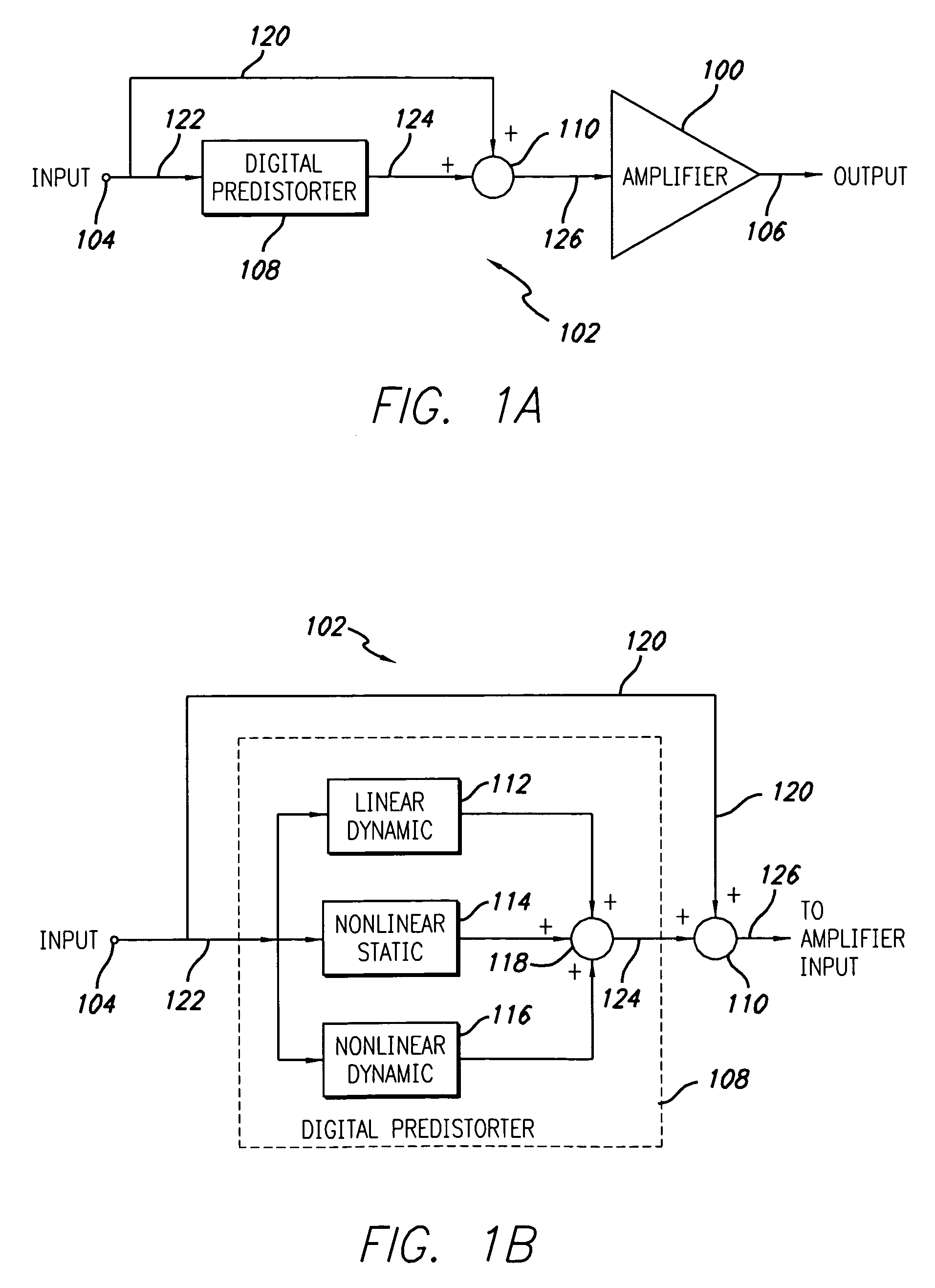
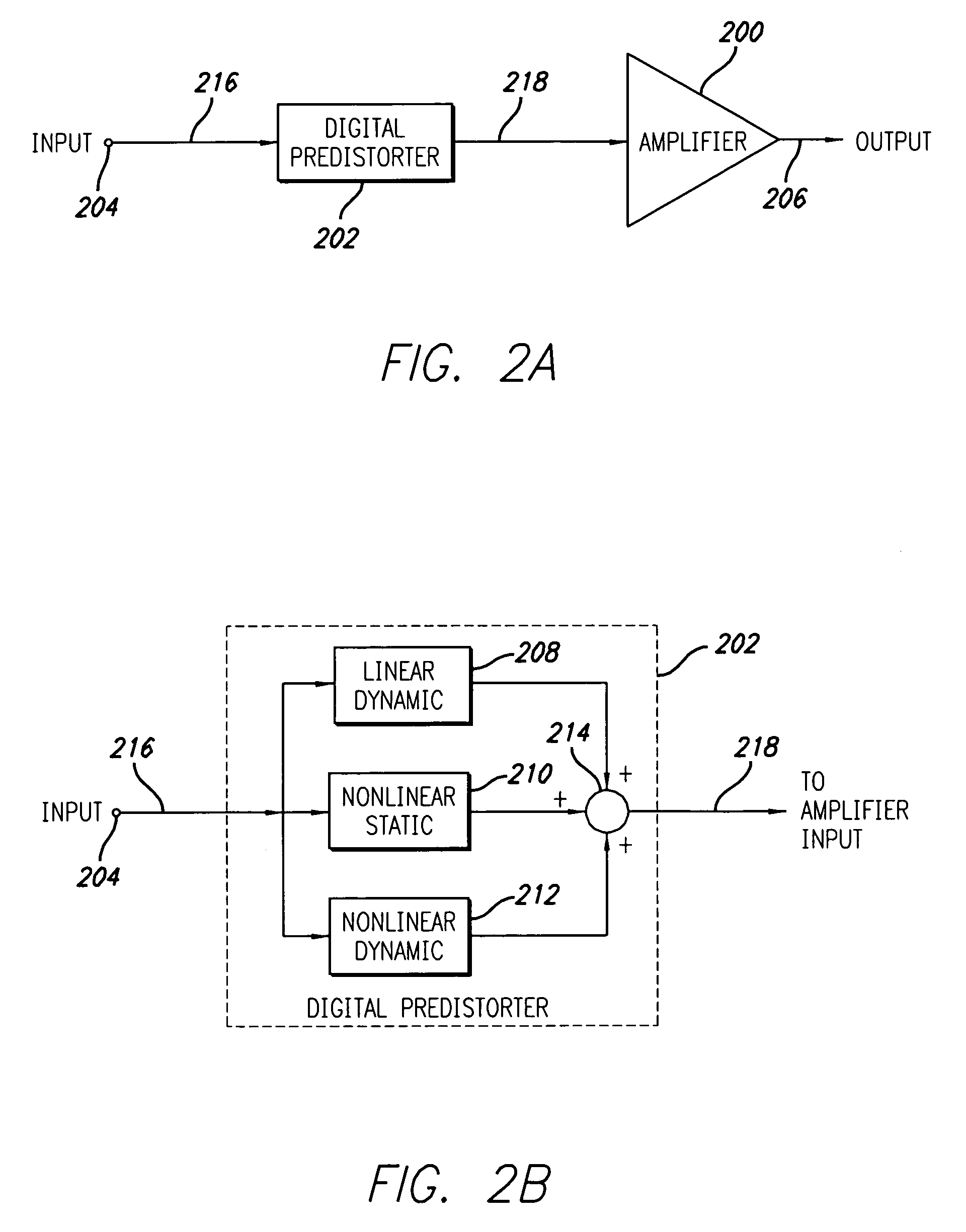
[0033]The present invention provides a digital predistortion system and method with enhanced distortion correction capabilities. The present invention further provides an improved predistortion linearized amplifier system and related method. FIGS. 1A and 1B show an additive predistortion system and predistortion linearized amplifier in accordance with a first embodiment of the present invention in which the distortion compensation signal is added (injected) digitally to the baseband modulation input to form the predistorted signal to drive the amplifier. FIGS. 2A and 2B show a multiplicative predistortion system and predistortion linearized amplifier in accordance with a second embodiment of the present invention in which the digital predistorter acts as a nonlinear operator in cascade with the amplifier.

[0034]Referring first to FIG. 1A, the predistortion linearized amplifier system in accordance with a first embodiment of the present invention includes an amplifier 100 which is pre...


PUM


Abstract

A system for linearizing RF amplifiers employing baseband predistortion techniques provides additive or multiplicative predistortion of the quadrature (I / Q) input signal. The predistorter uses a discrete-time polynomial kernel to model the inverse transfer characteristic of the amplifier, providing separate and simultaneous compensation for nonlinear static distortion, linear dynamic distortion and nonlinear dynamic effects including reactive electrical memory effects. A predistortion controller monitors and compares the amplifier output with the quadrature input signal to compute estimates of the residual output distortion of the amplifier. Output distortion estimates are used to adaptively compute the predistorter parameter values in response to changes in the amplifier's operating conditions. The computed values are used in the predistorter. The predistortion system of the invention may provide broadband linearization of RF amplification circuits including, but not limited to, dynamic load modulation amplifiers.

Description

RELATED APPLICATION INFORMATION[0001]The present application claims priority to provisional application Ser. No. 60 / 537,937 filed Jan. 21, 2004, the disclosure of which is incorporated by reference herein in its entirety.FIELD OF THE INVENTION[0002]The present invention is directed to predistortion linearization of high efficiency, high power RF amplifiers and related systems and methods.BACKGROUND, PRIOR ART AND RELATED INFORMATION[0003]Modern wireless communication systems employ spectrally efficient, digitally modulated signals with wide bandwidths and time-varying envelopes. Variations in the envelope magnitude of digital modulations generate distortion components at the output of the transmitter that are caused by the inherent nonlinearity of RF amplification circuits. Amplifier distortion produces a dilation of the spectrum of the input signal (“spectral regrowth”) which causes interference to communications in adjacent channels. Adjacent channel interference (ACI) is a highly...

Claims


Application Information

Patent Timeline
Patent Type & Authority Patents(United States)
IPC IPC(8): H04L25/49H03F1/32H04K1/02
CPCH03F1/3247H03F1/3252H03F1/3294H03F2200/102H03F2200/336H03F1/32
Inventor COVA, ARMANDOCARICHNER, SCOTT
Owner INTEL CORP
Learn More