
Filter system

a filter system and oil filter technology, applied in the field of particle filtration, oil deemulsification, oil coalescing and oil collecting systems, can solve the problems of high pressure pump and housing, cartridge and bag filter blinding, and each of the known systems has its drawbacks, and achieves the effect of convenient separation and small footprin

Inactive Publication Date: 2008-04-29
BANK OF AMERICA NAT TRUST & SAVINGS ASSOC
View PDF26 Cites 3 Cited by
  • Summary
  • Abstract
  • Description
  • Claims
  • Application Information

AI Technical Summary

Benefits of technology

"The patent describes a filter system that can separate oil from water with a high efficiency. The system uses a coiled tubular filter that can de-emulsify and coalesce oils, allowing them to be easily removed. The system is designed to be cost-effective and less susceptible to fouling and bacteria colonization. The technical effects of the invention include improved oil separation from contaminated oil-in-water emulsions, reduced environmental impact, and improved efficiency in industrial applications."

Problems solved by technology

However, each of these known systems has its drawbacks.
For example, cartridge and bag filters are subject to blinding by oil emulsions and contaminants and require high pressure pumps and housings.
Oil coalescing systems are relatively expensive and difficult to clean and usually require a relatively large dedicated floor space, and do not remove emulsified tramp oils.
Membrane filters are unreliable due to their sensitivity to fouling by various contaminants and damage by pH and temperature.
As the concentration of oil increases, the efficiency of the filtration system decreases (due to increased resistance across the membrane) and the membrane becomes increasingly susceptible to fouling.
Periodic change-out of the coolant results in labor time and costs, machine down-time, coolant costs and disposal costs.
Moreover, once the coolant is changed, it begins accumulating unwanted contaminants such that the quality of the coolant continually degrades until the next change-out.
These include using spinning discs near the surface of the membrane; however, these disks require relatively large amounts of energy and generate heat in the fluid.
The heat generated from the antifouling mechanisms tends to colonize bacteria and create offensive odors.
Further, membrane filtration systems cannot be used to filter emulsified oil coolants for reuse because the membrane blinds (clogs or fouls) when it is used to filter out finely divided oil-in-water emulsions.
With respect to oil-in-water emulsions, these are liquid systems that are particularly difficult to filter.
In such systems, tramp oils such as (other, undesirable) lubricating oils, hydraulic fluids and part coating oils (collectively contaminants) maybe present in the coolant system.
Floating oils can also form dry floating patches of material that are not effectively picked up by conventional skimming techniques.
However, oil skimmers do not remove emulsified tramp oils.

Method used


Image

  • Filter system
  • Filter system
  • Filter system

Examples


Embodiment Construction

[0033]While the present invention is susceptible of embodiment in various forms, there is shown in the drawings and will hereinafter be described a presently preferred embodiment with the understanding that the present disclosure is to be considered an exemplification of the invention and is not intended to limit the invention to the specific embodiment illustrated.

[0034]It should be further understood that the title of this section of this specification, namely, “Detailed Description Of The Invention”, relates to a requirement of the United States Patent Office, and does not imply, nor should be inferred to limit the subject matter disclosed herein.

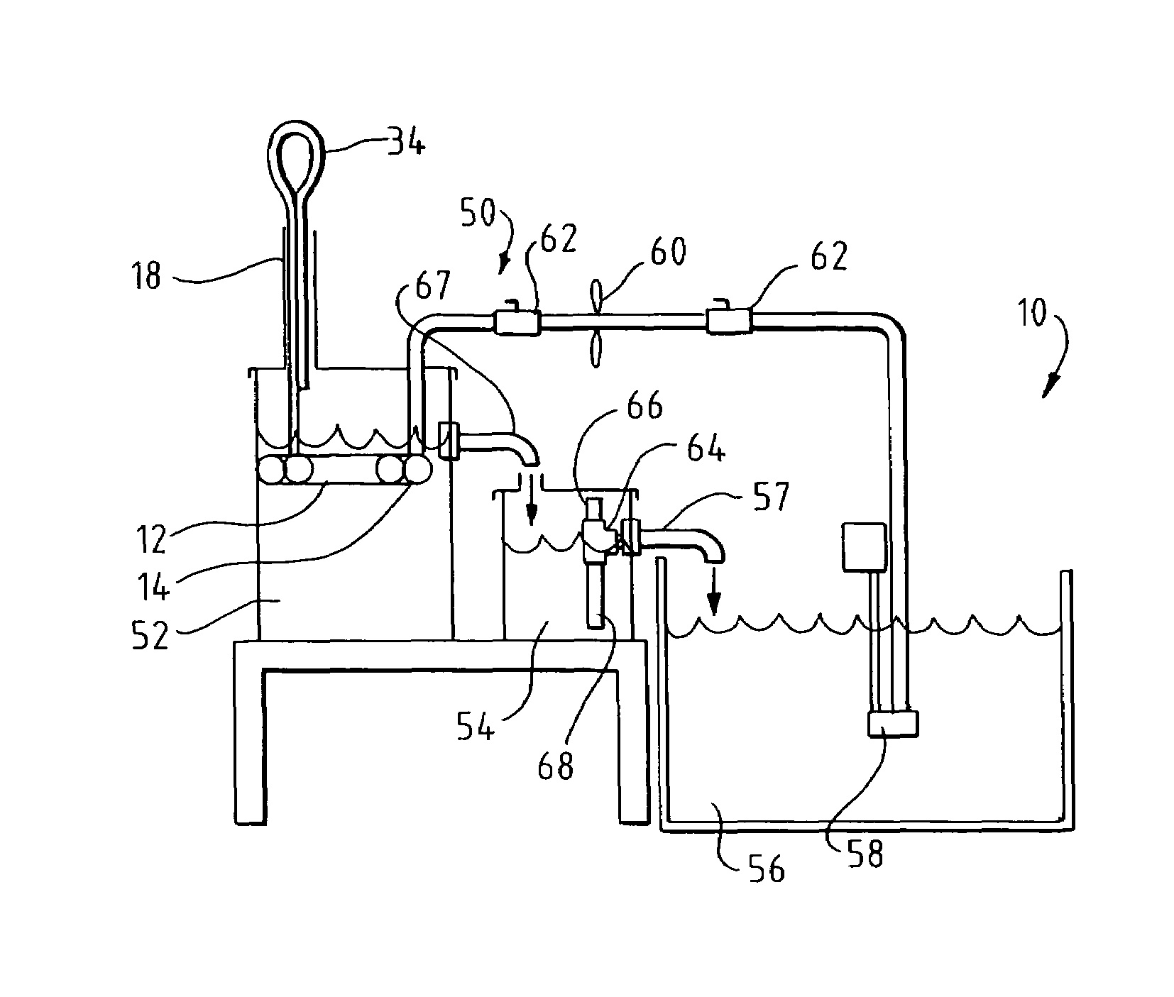
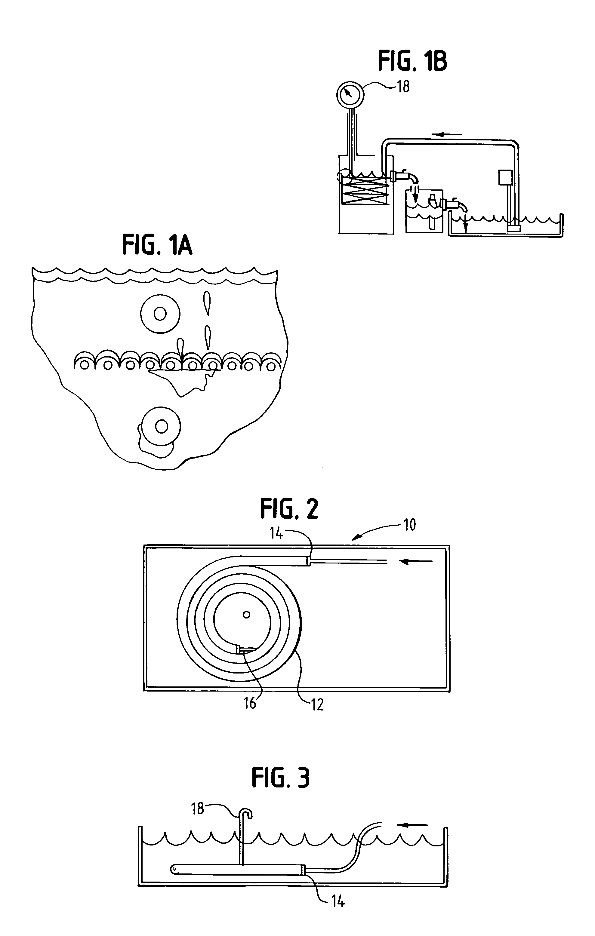
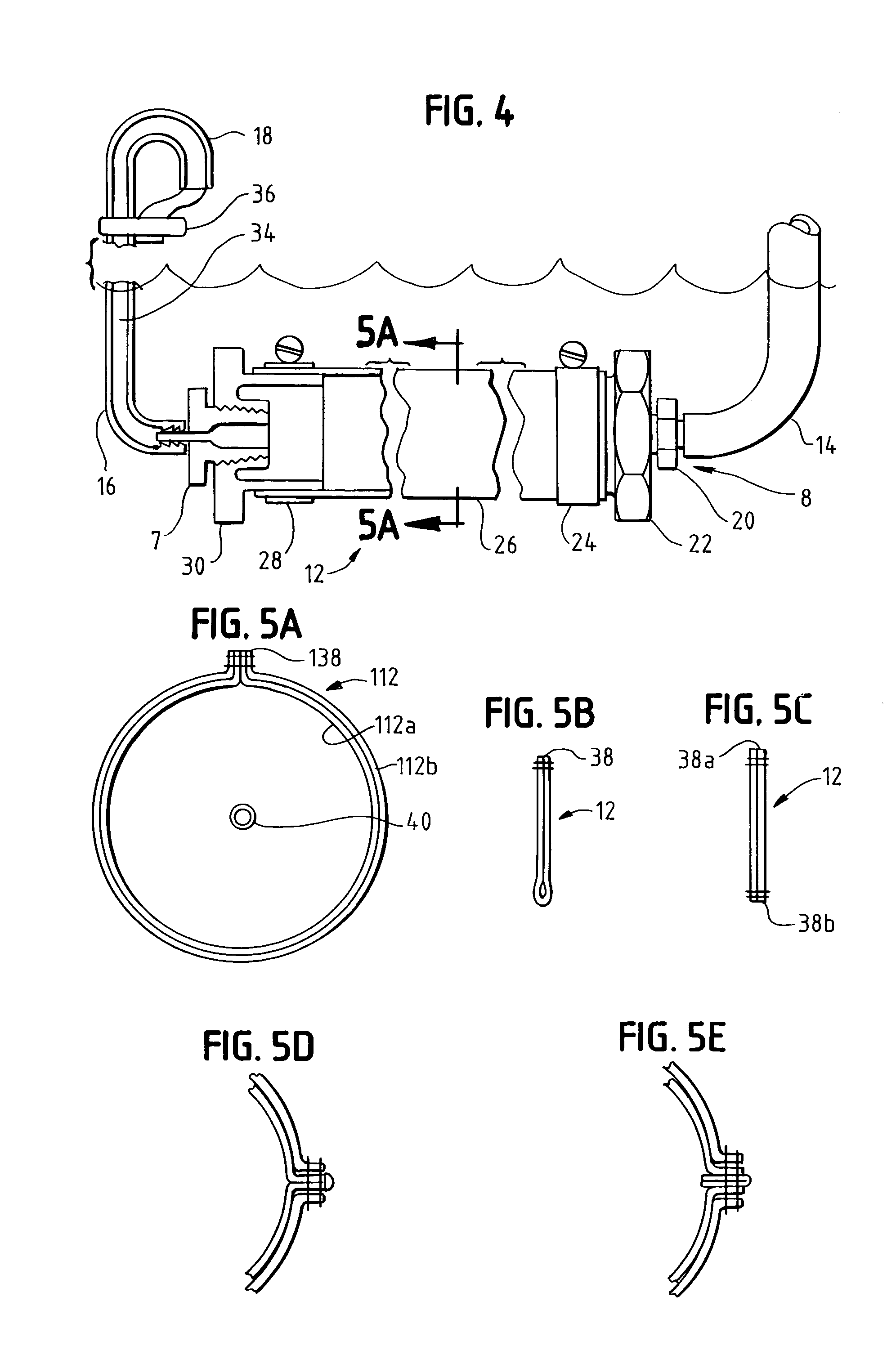
[0035]Referring now to the figures, and in particular to FIGS. 1B, 4, 6 and 11, there is shown a one embodiment of a coalescing / de-emulsifying coiled tubular filter system 10. The system 10 is configured to receive a contaminated liquid stream, such as an oil-in-water emulsion, de-emulsify the contaminants from the emulsion and pass both...


PUM

PropertyMeasurementUnit
weightaaaaaaaaaa
thickaaaaaaaaaa
discharge concentrationaaaaaaaaaa

Abstract

A filter system for receiving an oil-in-water emulsion contaminated with an emulsified contaminant oil, and separating the emulsified contaminant oil from the oil-in-water emulsion includes a filter media for receiving the oil-in-water emulsion and emulsified contaminant oil, having an inner filter element formed from a 95 percent single pass efficiency 48 micron (5 micron nominal) filtering material of needle punch polypropylene felt, an outer filter element formed from a 95 percent single pass efficiency 19 micron absolute filtering material of a polypropylene microfiber material and a porous spunbond polypropylene sandwiching the outer filter media. The filter element de-emulsifies the emulsified contaminant oil from the oil-in-water emulsion into the contaminant oil and the oil-in-water emulsion, separates the de-emulsified contaminant oil from the oil-in-water emulsion, coalesces the separated contaminant oil and passes both the coalesced de-emulsified contaminant oil and the oil-in-water emulsion. A first tank supports the filter element and is further configured to hold a quantity of the separated coalesced contaminant oil and the oil-in-water emulsion. The first tank has an overflow passing to a second tank. The second tank has an oil separation assembly for removing the oil-in-water emulsion from the contaminant oil and passing the oil-in-water emulsion therefrom. A method for separating the emulsified contaminant oil from the oil-in-water emulsion and recovering the oil-in-water emulsion is also disclosed.

Description

CROSS-REFERENCE TO RELATED APPLICATION DATA[0001]This application claims the benefit of priority of U.S. Provisional patent Application Ser. No. 60 / 367,441, filed Mar. 25, 2002.BACKGROUND OF THE INVENTION[0002]The present invention is directed to a particle filtration, oil de-emulsifying, oil coalescing and oil collecting system. More particularly, the present invention is directed to a particle filtration, oil de-emulsifying, oil coalescing and oil collecting system that uses a needle punch polymer primary filter and a microfiber polymer secondary filter in a coiled tubular arrangement.[0003]Devices, systems and methods for the removal of particles, free oil (such as dispersed, finely divided oil droplets), and emulsified oil contaminants in aqueous fluids is in widespread use in all types of commercial and industrial facilities. Known devices include cartridge and bag filters either permanently installed or as a part of portable systems, conventional oil coalescing systems that re...

Claims


Application Information

Patent Timeline
Patent Type & Authority Patents(United States)
IPC IPC(8): B01D17/02B01D36/04
CPCB01D17/0214B01D17/045Y10S210/05
Inventor LARSON, DOUGLAS ALAN
Owner BANK OF AMERICA NAT TRUST & SAVINGS ASSOC
Learn More