
Non-return valve for use in a molding system

a molding system and non-return valve technology, applied in the field of non-return valves, can solve the problems of large loss of productivity, inability to achieve and/or sustain an intimate face-seal, and degrade at an unacceptably fast rate under normal operating conditions, so as to reduce the loss of contact at the transient level, and restrict the backflow of melt therebetween

Inactive Publication Date: 2008-04-29
HUSKY INJECTION MOLDING SYST LTD
View PDF22 Cites 0 Cited by
  • Summary
  • Abstract
  • Description
  • Claims
  • Application Information

AI Technical Summary

Benefits of technology

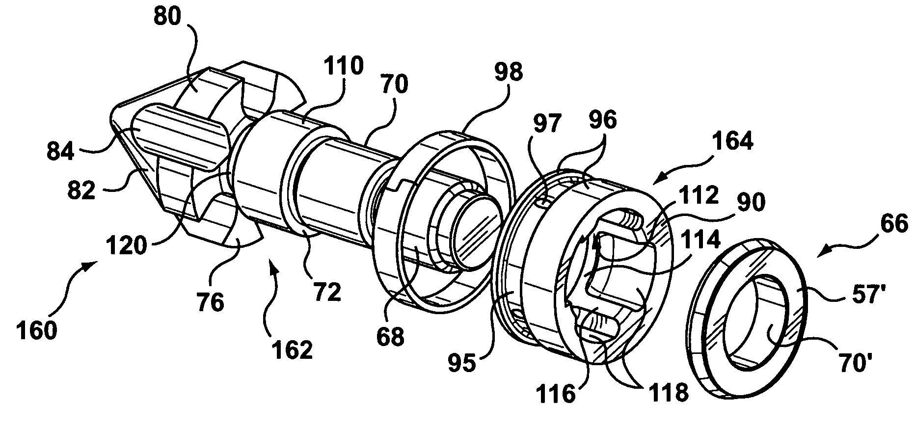
The present invention provides a non-return valve for a molding system that includes a spigot-seal to prevent melt from flowing back through the valve. The spigot-seal is created by complementary male and female spigot portions that are arranged close to each other and perpendicular to the longitudinal axis of the valve. The non-return valve also includes means for mutually aligning the tip and ring members to ensure consistent and even loading of the sealing and rear retaining portions. The spigot-seal and the means for mutual alignment work together to improve the performance and longevity of the non-return valve.

Problems solved by technology

Although it isn't well understood, a failure to achieve and / or sustain an intimate face-seal 91 for the duration of the injection step is thought to be caused by factors including melt non-uniformity and the injection dynamics.
Unfortunately, practical experience has also shown that the integrity of the retaining-sealing portions 90, 90, and hence the ability to achieve an intimate face-seal 91, degrades at an unacceptably fast rate under normal operating conditions.
This servicing requirement incurs large costs in lost productivity (i.e. low system availability) and need for highly skilled technical labor.

Method used


Image

  • Non-return valve for use in a molding system
  • Non-return valve for use in a molding system
  • Non-return valve for use in a molding system

Examples


Embodiment Construction

)

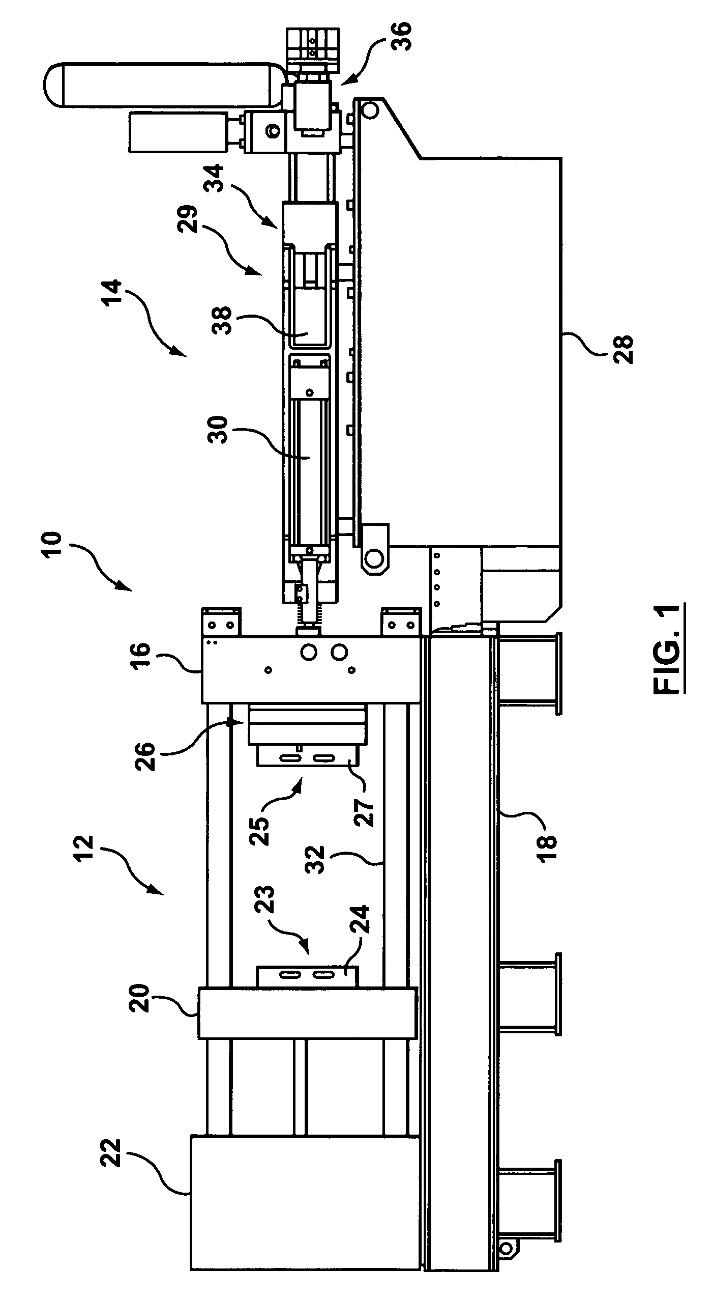
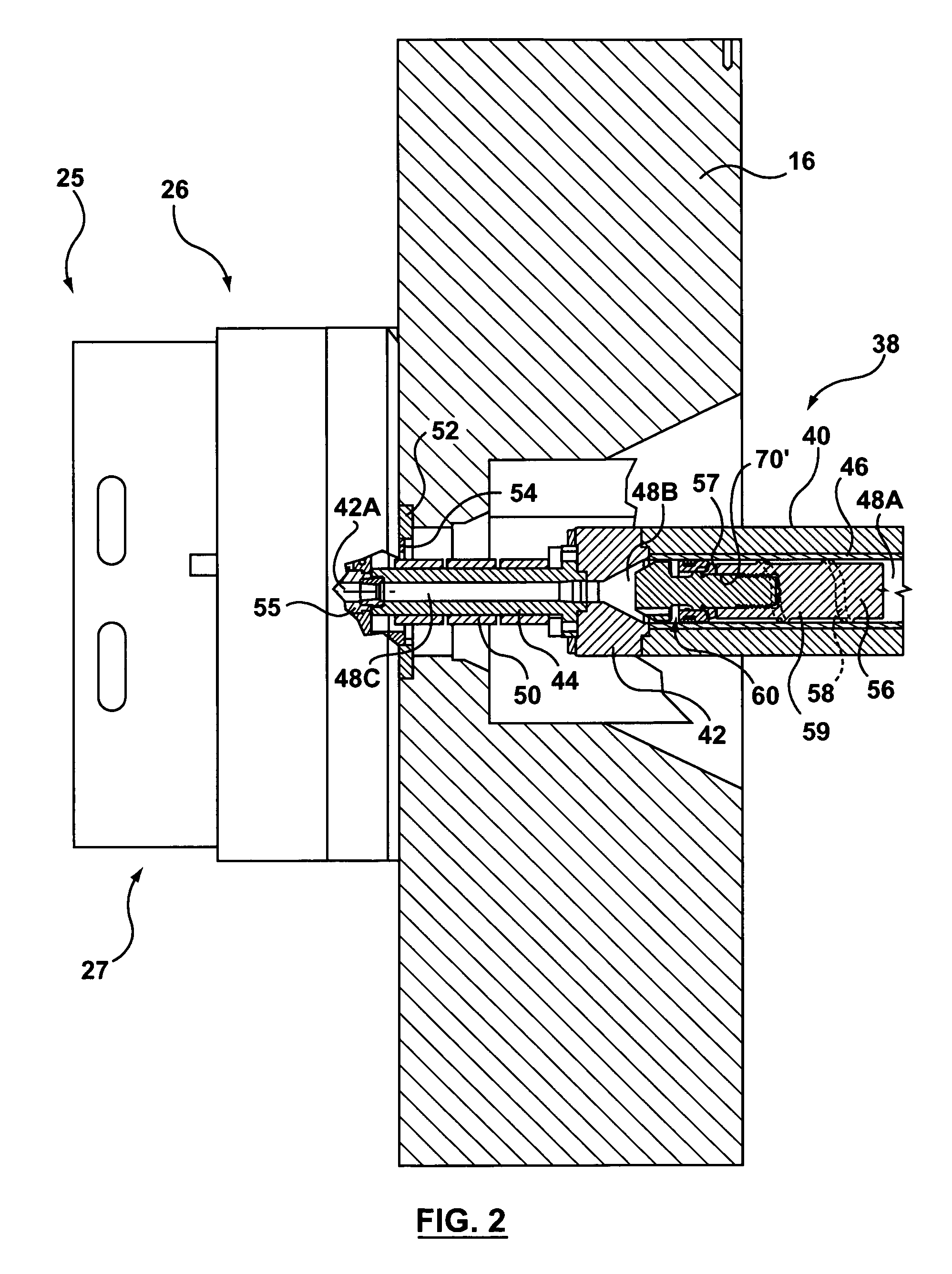
[0065]With reference to FIGS. 1, 5A, 5B, 5C, &5D, a non-return valve in accordance with a first embodiment of the present invention is shown that is configured for use in a barrel assembly 38 of an injection molding machine 10. The non-return valve 160 includes: a tip member 162 which is configured to be retained in the forward portion of the screw 56; a ring member 164, slidably arranged on the tip member 162, that is configured to cooperate with the tip member 162 between a recovery and an injection position defined therealong; and a flange member 166, arranged on a rear portion of the tip member 162, behind the ring member 164.

[0066]The tip member 162 comprises a cylindrical body 63 with a conical tip flange 81 and a cylindrical spigot flange 173 arranged around a forward and mid-section, respectively, thereon. Along the length of the tip member 162 are functional portions that include, listed from the rear forward, a screw coupling portion 68, an aligning portion 70, a seat por...


PUM

PropertyMeasurementUnit
melt temperatureaaaaaaaaaa
meltaaaaaaaaaa
pressureaaaaaaaaaa

Abstract

The present invention relates to a non-return valve that can be configured for use anywhere along a molding material flow path in a molding system. The non-return valve of the present invention includes an improved means to restrict the backflow of melt therethrough during injection. In particular, a spigot-seal is configurable, during injection, between overlapping, closely-spaced, and mutually parallel complementary male and female spigot portions that are configured between complementary valve members. The spigot-seal advantageously maintains an effective backflow restriction even in the eventuality of transient movement between the spigot portions during injection. Preferably, the non-return valve of the present invention is also configured to include a means for mutually aligning and / or guiding the complementary valve components that ensures a proper alignment between the complementary spigot portions, and may also serve to improve the function and longevity of a face-seal, when present. The non-return valve of the present invention provides particularly advantageous utility when configured for use in a barrel assembly of an injection unit for the injection molding of a metal alloy.

Description

TECHNICAL FIELD[0001]The present invention relates to a non-return valve that can be configured for use anywhere along a molding material flow path in a molding system. In further detail, the non-return valve of the present invention may be configured for use in a barrel assembly of an injection molding machine. More particularly, the non-return valve of the present invention may be configured for use in an injection molding system for the molding of metal.BACKGROUND OF THE INVENTION[0002]The structure and operation of the present invention will be explained, hereinafter, within the context of improving the function and durability of a non-return valve that is configured for use in a barrel assembly of an injection molding system for the molding of a metal alloy, such as those of Magnesium, in a semi-solid (i.e. thixotropic) state. A detailed description of the construction and operation of several of such injection molding systems is available with reference to U.S. Pat. Nos. 5,040...

Claims


Application Information

Patent Timeline
Patent Type & Authority Patents(United States)
IPC IPC(8): F16K47/00F16L55/02B22D17/20B28B17/00B29C45/23B29C45/52F16K15/02
CPCB22D17/2061F16K15/02B29C45/52Y10T137/88022
Inventor MANDA, JAN M.WEIR, SEANPINET, PIERRE JEAN
Owner HUSKY INJECTION MOLDING SYST LTD
Learn More