
Channel equalisation

a channel equalisation and channel equalisation technology, applied in the field of channel equalisation methods and apparatuses, can solve the problems of affecting the orthogonality of the signals received by the mobile users, and affecting the performance of the system, so as to reduce the interference of multiple accesses and demodulate the equaliser output

Inactive Publication Date: 2008-04-22
SONY CORP
View PDF11 Cites 4 Cited by
  • Summary
  • Abstract
  • Description
  • Claims
  • Application Information

AI Technical Summary

Benefits of technology

This approach enhances the performance of CDMA receivers by reducing multiple access interference and improving bit error rate performance, even in fast-changing channels, by dynamically adjusting the equalizer length based on instantaneous signal-to-noise ratios.

Problems solved by technology

While the transmitted signals for the users within a cell are orthogonal to each other, the multi-path propagation between the base station and the users seriously disrupts the orthogonality in the signals received by the mobile users.
Interference between the signals for different users gives rise to what is known as multiple access interference (MAI).
The presence of MAI significantly degrades system performance.
However, over a time-varying channel, where deep fading occurs the signal-to-noise ratio can be very low during the deep fading period.
Adaptive algorithms do not work very well if there is a low signal-to-noise ratio.
Although the periods of low signal-to-noise ratio caused by deep fading do not last long, the existence of low signal-to-noise ratio periods still degrades the convergence of adaptive algorithms.
The faster the multi-path fading is, the more frequently low signal-to-noise ratio events occur, and the worse the adaptive equaliser performance becomes.
Deep fading is one of the main reasons why adaptive equalisers perform so badly when used in conjunction with time-varying channels.
However we have appreciated that this assumption is based on the expectation that the true values for all weights can be obtained, whereas in a practical system the estimates for weights are noisy.
Otherwise, that is where the instantaneous signal-to-noise ratio is low, the small-value weights will lead to a worse result and should be removed from the equaliser.

Method used


Image

  • Channel equalisation
  • Channel equalisation
  • Channel equalisation

Examples


Embodiment Construction

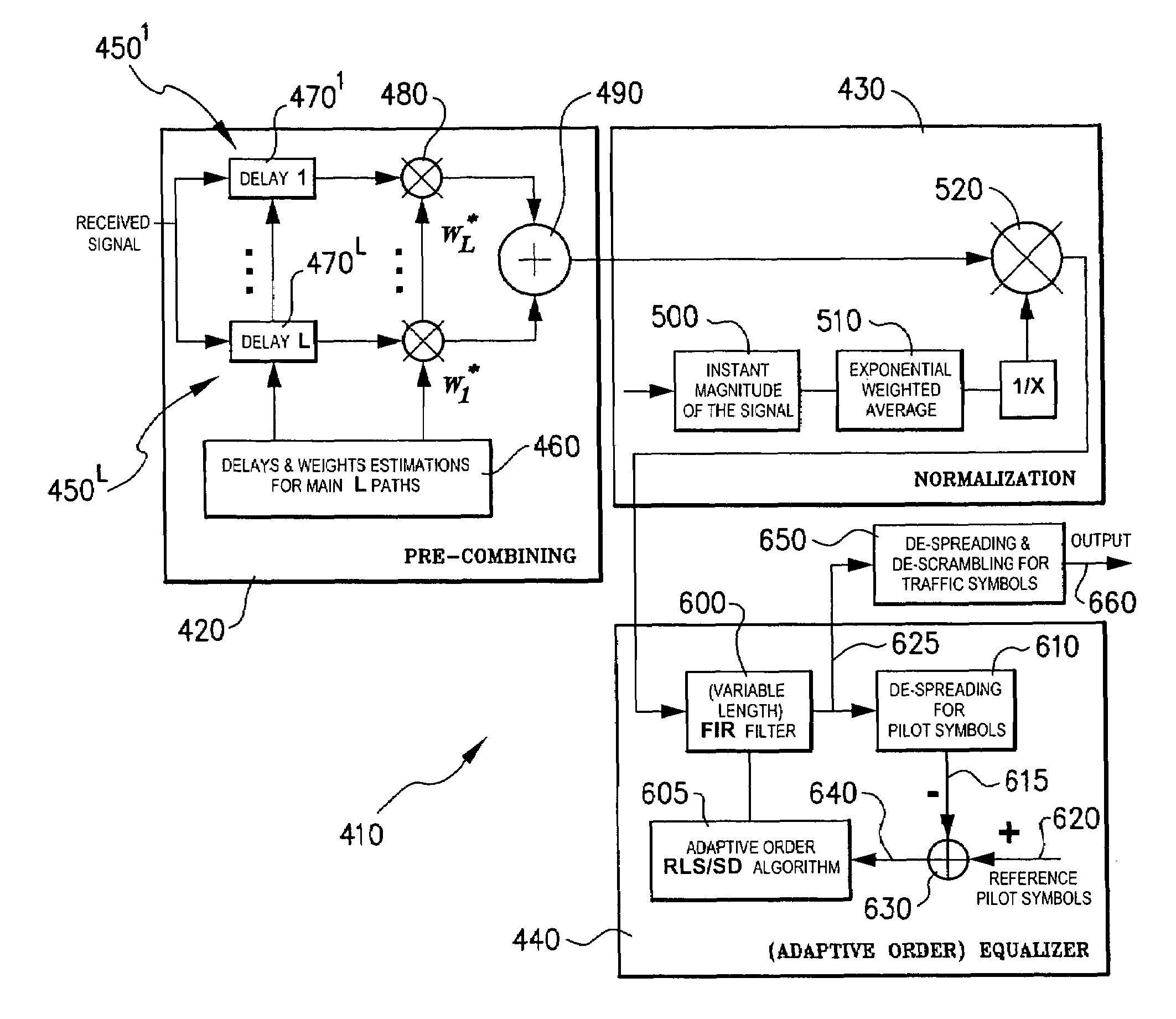
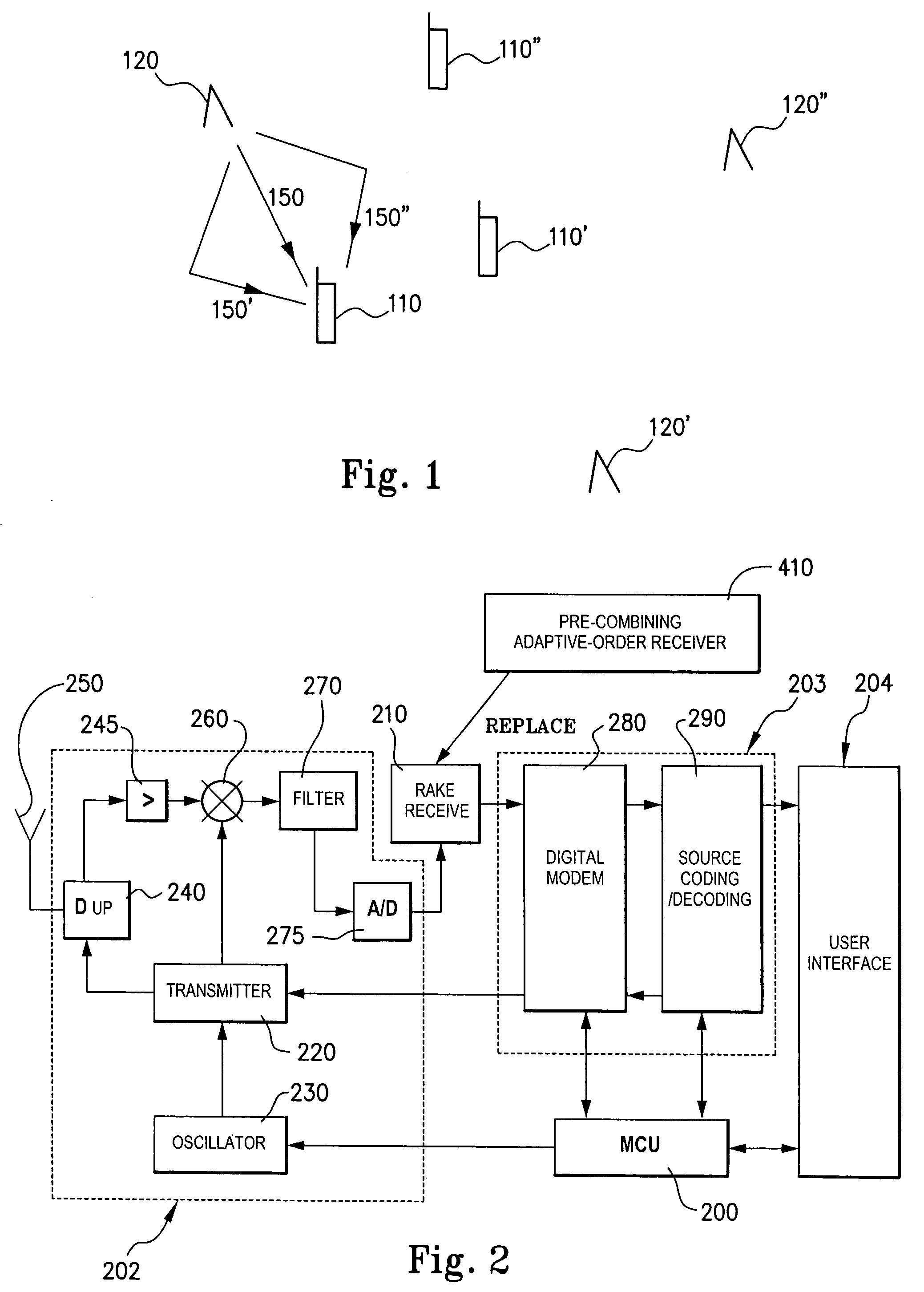
[0030]FIG. 1 is a schematic diagram of a cellular radio communications system 100 which uses a multiple access technology such as wideband CDMA (WCDMA) for communication between users of user terminals 110 (for example, mobile phones) and base stations 120. A plurality of base stations 120, 120′ and 120″ are provided for wireless communication with a greater plurality of mobile terminals, 110, 110′, 110″, etc. Signals from a mobile terminal 110 travel over free space on the uplink to base station 120. From the base station 120 the signals pass to a base station controller. The base station controller may be coupled to a mobile switching center (MSC), and MSC may be connected in turn to a fixed communications network such as the public switched telephone network (PSTN) to permit signals from the user terminal 110 to be passed to a subscriber of the fixed network and vice versa. The fixed communications network will also carry signals from the user terminal 110 to other users or subsc...


PUM


Abstract

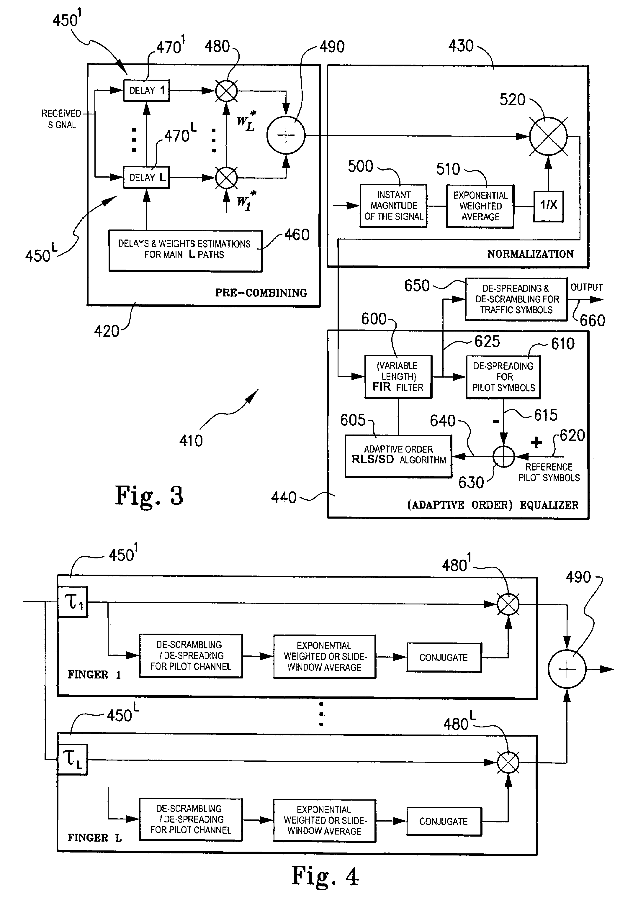
A method of reducing multiple access interference in a CDMA radio system uses a plurality of rake fingers to pre-process received signals but without demodulation or de-spreading. The outputs of the rake fingers are combined, normalised and then processed by an adaptive equaliser to recover orthogonality lost in transmission. The equaliser output is then subject to de-spreading and de-scrambling to recover the desired user signals. The equaliser is preferably adaptive order, the length being adapted in dependence upon the instantaneous signal to noise ratio.

Description

FIELD OF THE INVENTION[0001]The present invention relates to methods and apparatus for channel equalisation.BACKGROUND OF THE INVENTION[0002]In several fields of communication there exists the need to deal at a receiver with the time-varying nature of a communications channel.[0003]One such field of communication is in code division multiple access (CDMA). CDMA is used in the cdmaOne system (IS-95) and will be used in the so-called third generation (3G) mobile system. Each of these systems uses direct-sequence code division multiple access (DS-CDMA) in which orthogonal spreading codes are used on the down link to multiplex signals to multiple users. The spread signals of all users are combined together synchronously. The sum is scrambled by a long pseudo-noise code and transmitted from a base station. While the transmitted signals for the users within a cell are orthogonal to each other, the multi-path propagation between the base station and the users seriously disrupts the orthogo...

Claims


Application Information

Patent Timeline
Patent Type & Authority Patents(United States)
IPC IPC(8): H04B1/707H04L25/03H04L27/30
CPCH04B1/7103H04B1/712H04L2025/03375H04L2025/03477H04L2025/03585H04L2025/03617
Inventor MA, YUGANG
Owner SONY CORP
Learn More