Substrate processing apparatus and maintenance method therefor

a substrate processing and substrate technology, applied in the field of substrate processing apparatuses, can solve the problems of increasing the cost of ownership (coo) and achieve the effect of increasing the cost of ownership and lowering the processing efficiency

Inactive Publication Date: 2008-04-22
SUMITOMO HEAVY IND LTD
View PDF7 Cites 2 Cited by
  • Summary
  • Abstract
  • Description
  • Claims
  • Application Information

AI Technical Summary

Benefits of technology

[0006]The maintenance utilizing such a maintenance jig requires a large maintenance space and a commensurate space for keeping such a maintenance jig, which may increase the cost of ownership (COO). Also, it takes considerable time to install the jig for maintenance, which elongates the processing stop period (downtime), thereby lowering the processing efficiency.
[0007]For solving the problems mentioned above, it is an object of the present invention to provide a substrate processing apparatus which can reduce the cost of ownership and improve the substrate processing efficiency, and a maintenance method therefor.
[0009]In the substrate processing apparatus, since the elevator for moving the lid is disposed integrally with the chamber, the maintenance space becomes smaller than that conventionally needed, and no space is necessary for keeping the elevator, whereby the cost of ownership is cut down. Also, since the elevator is integrated with the chamber, the time conventionally required for installing jigs for maintenance is unnecessary, which shortens the processing stop period (downtime), thus improving the substrate processing efficiency.
[0013]The elevator may further has a second pole erected from the upper side of the container so as to extend vertically; a second tubular member inserted onto the second pole and held by the upper lid so as to be rotatable about the second pole; a third thread provided on an inner face of the second tubular member; a fourth thread provided on a surface of the second pole and adapted to engage the third thread; and a power transmitting mechanism, disposed between the first and second tubular members, for rotating the second tubular member in synchronization with the first tubular member. In this configuration, the first tubular member is rotated by the turning force from the driving source, and this rotation is transmitted to the second tubular member by way of the power transmitting mechanism, whereby the first and second tubular members rotate in synchronization. Therefore, the first and second tubular members vertically ascend / descend at the same pace along the first and second poles because of the respective engagements between the first and second threads and between the third and fourth threads. As a result, the upper lid ascends / descends in a stable state.
[0014]The substrate processing apparatus may further comprise a tubular cover detachably attached to the first pole so as to cover the surface of the first pole. This can protect the grease-coated surface of the first pole. Also, when the lower part of the first pole, i.e., the part lower than the upper lid, is protected by the cover after the upper lid is ascended, the cover can function as a support member, which prevents the upper lid from dropping out.
[0017]In this method, the maintenance within the container is carried out while in a state where the upper lid is raised and held at a position separated by a predetermined distance from above the container. Therefore, the space above the chamber is effectively utilized, so as to reduce the maintenance space, thereby cutting down the cost of ownership. Also, since the maintenance is started and terminated by simply moving the upper lid up and down on the upper side of the container, the processing stop period (downtime) can be shortened, which improves the substrate processing efficiency.

Problems solved by technology

The maintenance utilizing such a maintenance jig requires a large maintenance space and a commensurate space for keeping such a maintenance jig, which may increase the cost of ownership (COO).
Also, it takes considerable time to install the jig for maintenance, which elongates the processing stop period (downtime), thereby lowering the processing efficiency.

Method used


Image

  • Substrate processing apparatus and maintenance method therefor
  • Substrate processing apparatus and maintenance method therefor
  • Substrate processing apparatus and maintenance method therefor

Examples


Embodiment Construction

[0030]In the following, embodiments of the present invention will be explained with reference to the accompanying drawings. In the explanation of the drawings, constituents identical to each other will be referred to with numerals identical to each other without repeating their overlapping descriptions.

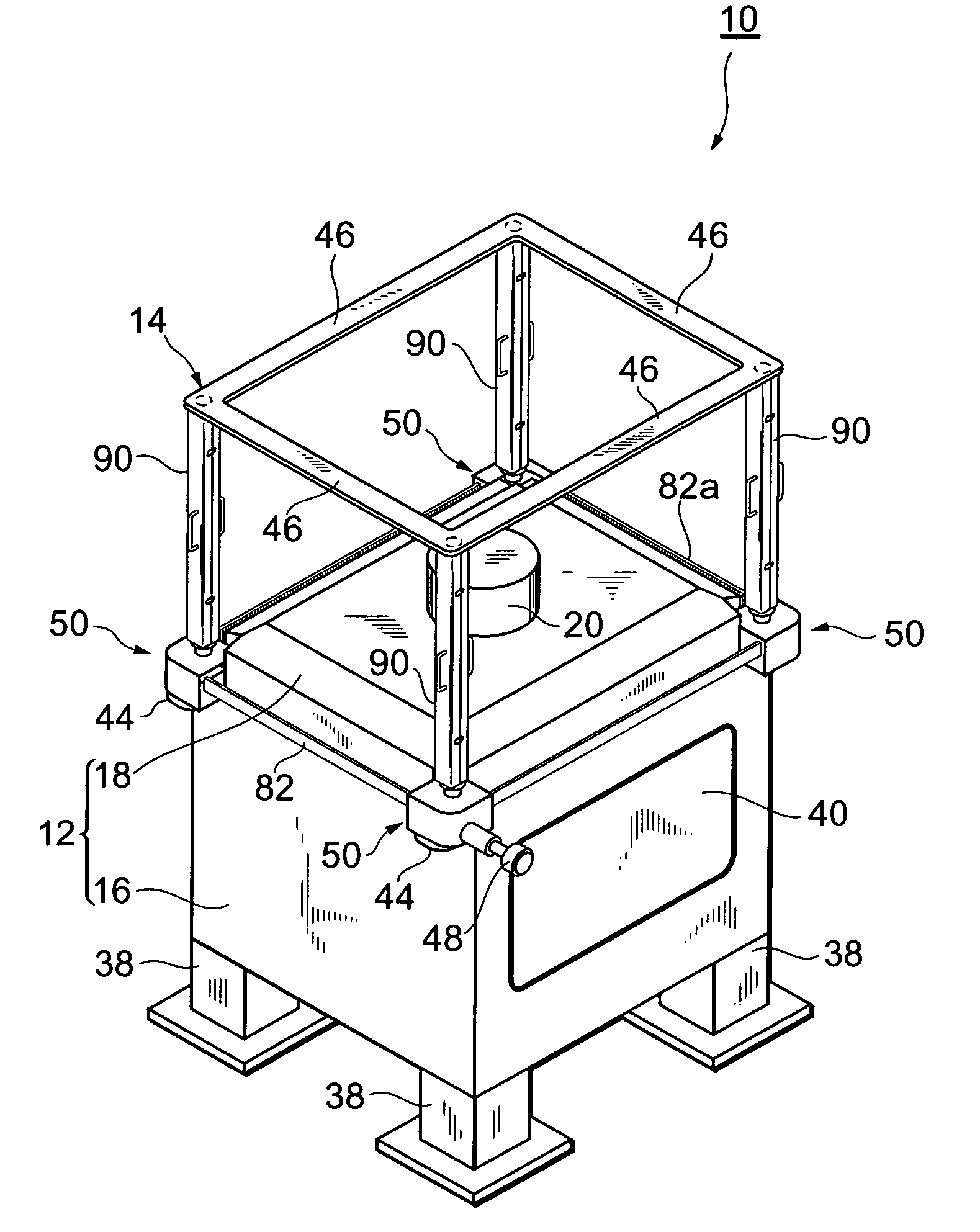
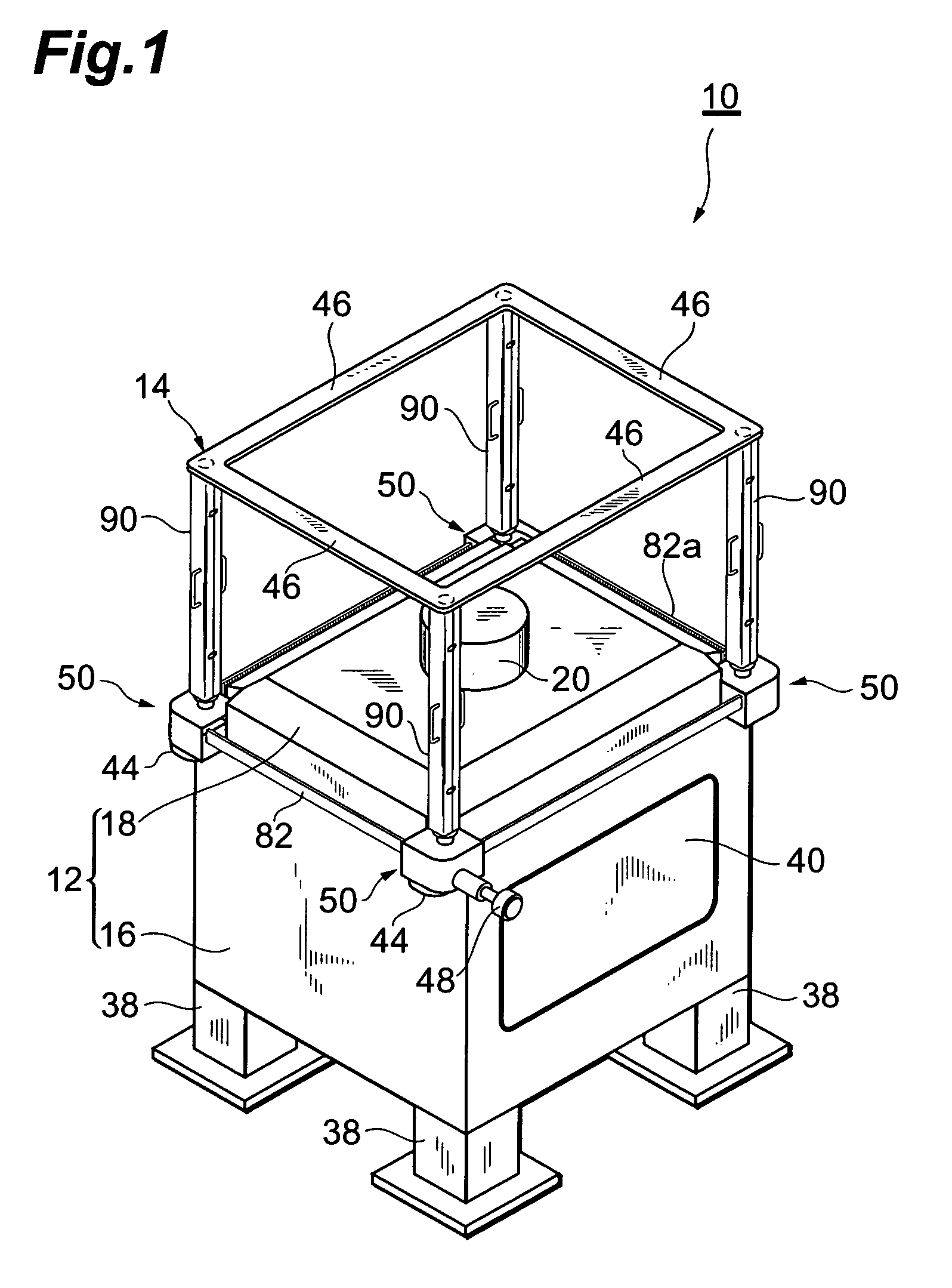
[0031]FIG. 1 is a perspective view showing the configuration of an electron beam exposure apparatus (which may simply be referred to as “exposure apparatus” in the following) as the substrate processing apparatus in accordance with an embodiment. As shown in FIG. 1, this exposure apparatus 10 comprises a vacuum chamber 12 and an elevator 14.

[0032]The vacuum chamber 12 comprises a container 16 having an open upper end, and an upper lid 18 for closing the upper opening of the container 16.

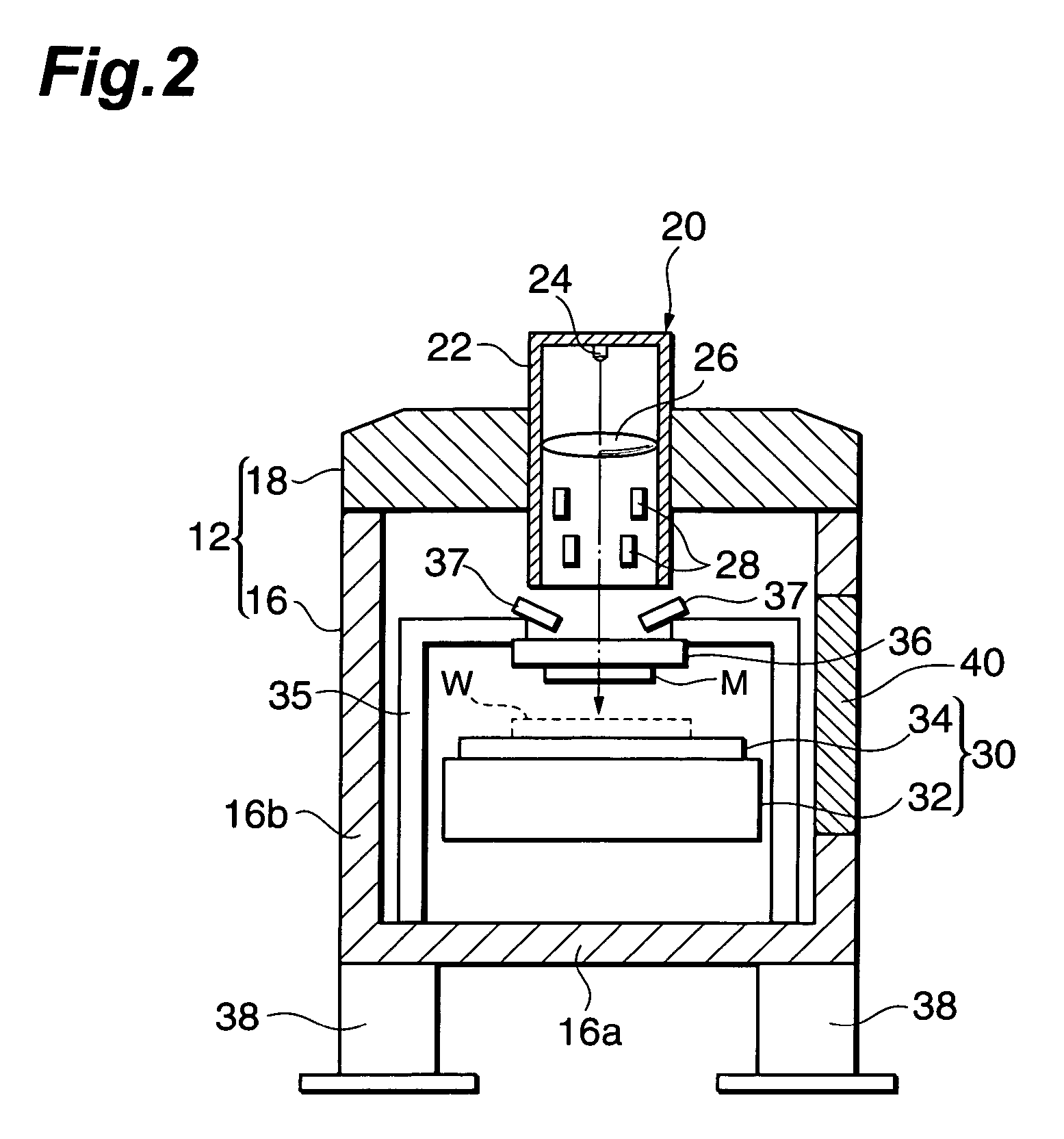
[0033]The upper lid 18 has a rectangular horizontal cross section, whereas an electron beam irradiating part 20 for emitting an electron beam is disposed at the center thereof. As shown in FIG. 2, the ...


PUM


Abstract

A substrate processing apparatus comprises a chamber. The chamber includes a container and an upper lid for closing an upper opening of the container. On the upper side of the chamber, an elevator for vertically moving the upper lid is disposed integrally with the chamber.

Description

BACKGROUND OF THE INVENTION[0001]1. Field of the Invention[0002]The present invention relates to a substrate processing apparatus equipped with a chamber for processing a substrate such as a semiconductor wafer, and a maintenance method therefor.[0003]2. Related Background Art[0004]An exposure apparatus utilizing en electron beam is equipped with a vacuum chamber. The vacuum chamber comprises a container and an upper lid for covering an upper opening of the container. The upper lid is provided with an irradiating part for emitting the electron beam, whereas an alignment mechanism for positioning a mask and a substrate is disposed within the container (see, for example, Reference 1: Hiroshi NOZUE and four others, “Development of next-generation electron-beam exposure systems”, OYO BUTURI, Vol.71, No.4, p.421-424 (2002)).[0005]In such an exposure apparatus, large-scale maintenance has been carried out in a state where a maintenance jig such as a jib crane or portal crane is used so as...

Claims


Application Information

Patent Timeline
IPC IPC(8): H01L21/302H01J37/305H01L21/00H01L21/027H01L21/205H01L21/3065H01L21/677
CPCH01L21/67126H01L21/67751H01L21/67757H01L21/67772G03F7/70808
Inventor TANAKA, TOSHIHARUIIO, ITSUSHI
Owner SUMITOMO HEAVY IND LTD
Why Eureka
Try Eureka