Air valve coupling method and apparatus

a technology of air valves and coupling methods, applied in the direction of water supply installation, manufacturing tools, transportation and packaging, etc., can solve the problem of difficult to keep them clean

Active Publication Date: 2008-04-22
BRYAN STEVE M
View PDF16 Cites 12 Cited by
  • Summary
  • Abstract
  • Description
  • Claims
  • Application Information

AI Technical Summary

Benefits of technology

[0012]An advantage of the present invention is that the flow of air is utilized to clean the valve prior to an engaging into a sealed relationship.
[0013]Another advantage of the present invention is that one valve assembly is extended by the removal of an opposing air pressure.
[0014]Another advantage of the present invention is that air is utilized to extend a portion of one valve assembly.

Problems solved by technology

A problem with the air coupling devices is that it is difficult to keep them clean and to ensure that no debris enters the air turbine.

Method used


Image

  • Air valve coupling method and apparatus
  • Air valve coupling method and apparatus
  • Air valve coupling method and apparatus

Examples


Embodiment Construction

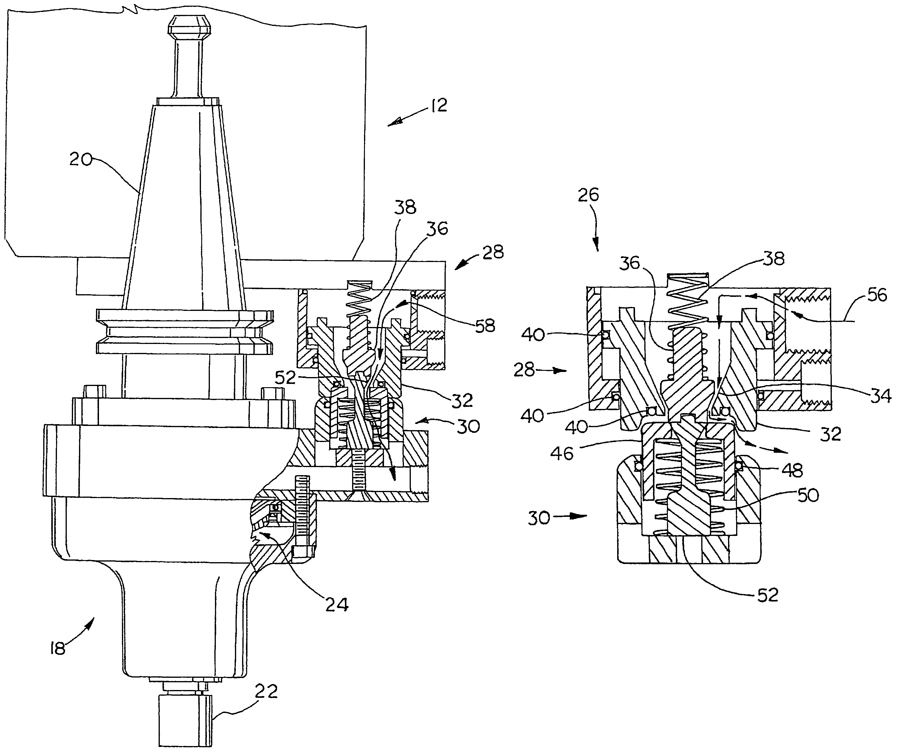
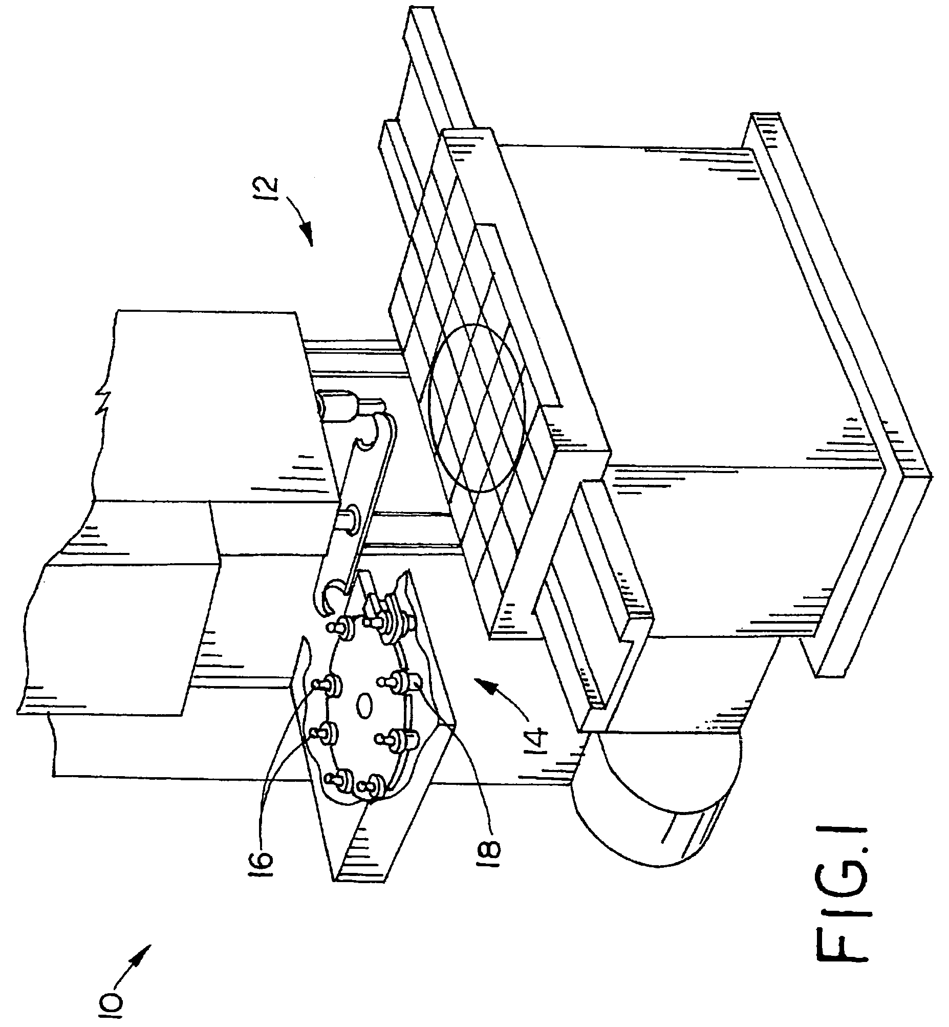
[0021]Referring now to the drawings, and more particularly to FIG. 1, there is shown a machining center 10 having a machining head 12, a tool changer 14, tools 16 and an air driven tool 18. Machining center 10 is under programmable control of a controller, not shown, that operates the relative position of an X-Y table, the spindle operation is in a Z direction. The spindle of machine head 12 receives tools 16 and 18, which are shaped to a uniform adaptive feature so that they can be readily inserted into the spindle of machine head 12. Tool changer 14 removes tools from the spindle and picks up tools 16 or 18 from a tool storage device. Air driven tool 18 is substantially similar to tool 16 except that air driven tool 18 has a valve system attached thereto. Machining center 10 is programmed to locate a cutting edge of a tool 16 or 18 in an appropriate position for cutting material mounted on the X-Y table.

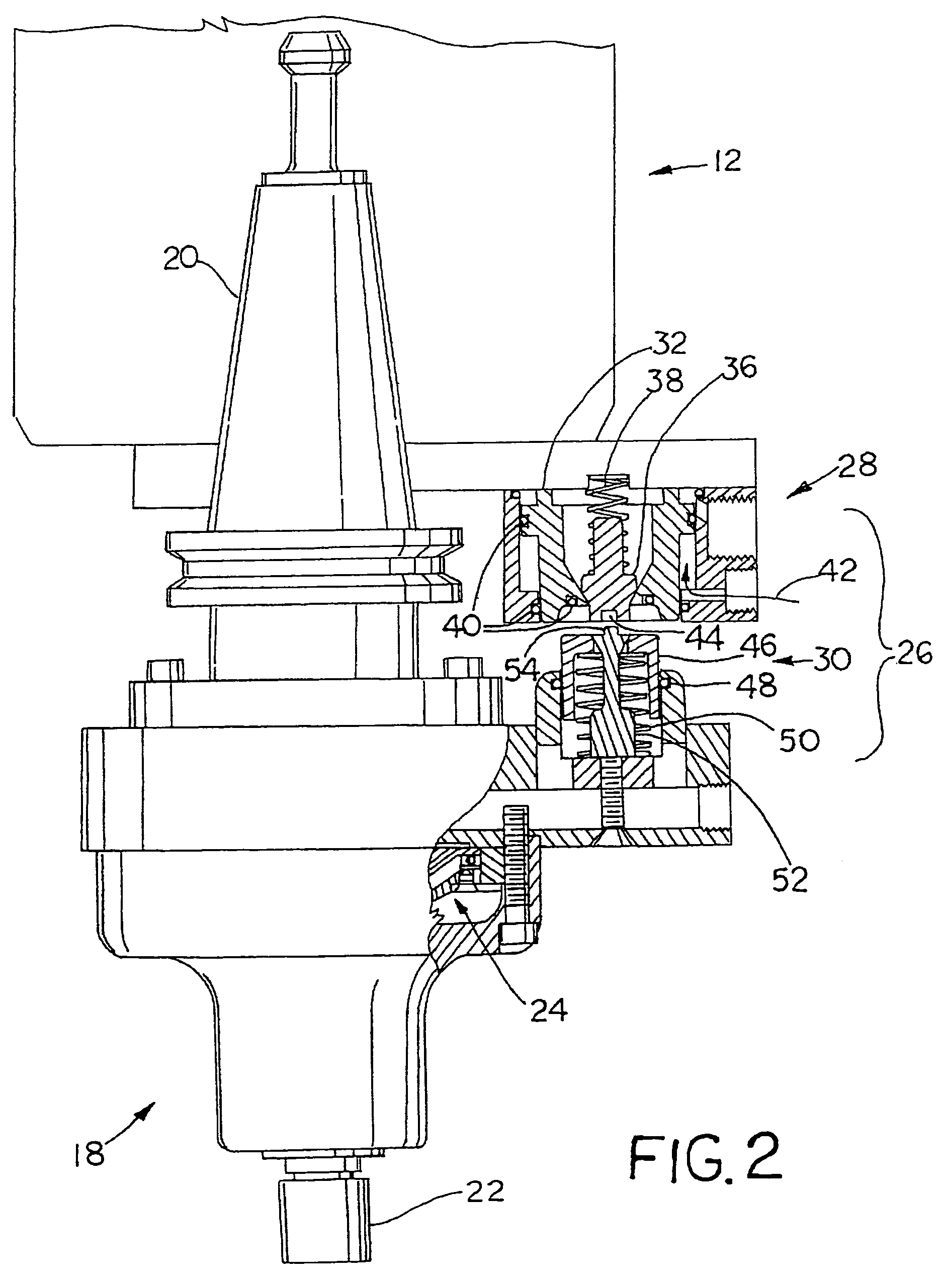
[0022]Now, additionally referring to FIGS. 2-4 air driven tool 18 includes a c...


PUM

PropertyMeasurementUnit
biasing forceaaaaaaaaaa
forceaaaaaaaaaa
speedaaaaaaaaaa

Abstract

A machining center including a machining head, a tool changer, an air driven tool and an air valve system. The air driven tool is connectable to the machine head by action of the tool changer. The air valve system has a first portion associated with the machining head and a second portion associated with the air driven tool. The first portion and the second portion include a connection therebetween having an airflow across the connection before the connection seals.

Description

CROSS REFERENCE TO RELATED APPLICATIONS[0001]This is a non-provisional application based upon U.S. provisional patent application Ser. No. 60 / 680,161, entitled “AIR TURBINE COUPLER”, filed May 12, 2005.BACKGROUND OF THE INVENTION[0002]1. Field of the Invention[0003]The present invention relates to the coupling of an air valve assembly, and, more particularly, to coupling an air valve assembly of a machining center.[0004]2. Description of the Related Art[0005]It is known to provide a spindle unit for a machine tool in which the tool holding end of the spindle has a tapered socket in its nose to receive and hold a tool holder provided with an adapter. The adapter may be engaged with finger hooks carried by a drawbar so that the finger hooks are engaged and the drawbar is pulled inwardly by a spring mechanism of the tool holder to hold the tool. To release the tool holder for removal from the spindle it is often necessary to reverse the operation and push the drawbar inwardly a substan...

Claims


Application Information

Patent Timeline
Patent Type & Authority Patents(United States)
IPC IPC(8): B23C5/26B23Q11/00B23Q3/12
CPCB23B31/261B23Q1/0018B23Q5/048Y10T483/15Y10T409/303752Y10T483/1755Y10T409/304088Y10T409/309296B23Q2220/008Y10T137/0419Y10T137/043Y10T137/0491Y10T137/4245Y10T137/87957Y10T137/87965
Inventor BRYAN, STEVE M.
Owner BRYAN STEVE M
Why Eureka
Try Eureka