Delay calibration in polar modulation transmitters
a polar modulation and delay technology, applied in the field of polar modulation transmitter delay calibration, can solve the problems of delaying the path delay affecting the power ratio of adjacent channels, and affecting the accuracy of amplitude and phase signals
- Summary
- Abstract
- Description
- Claims
- Application Information
AI Technical Summary
Benefits of technology
Problems solved by technology
Method used
Image
Examples
Embodiment Construction
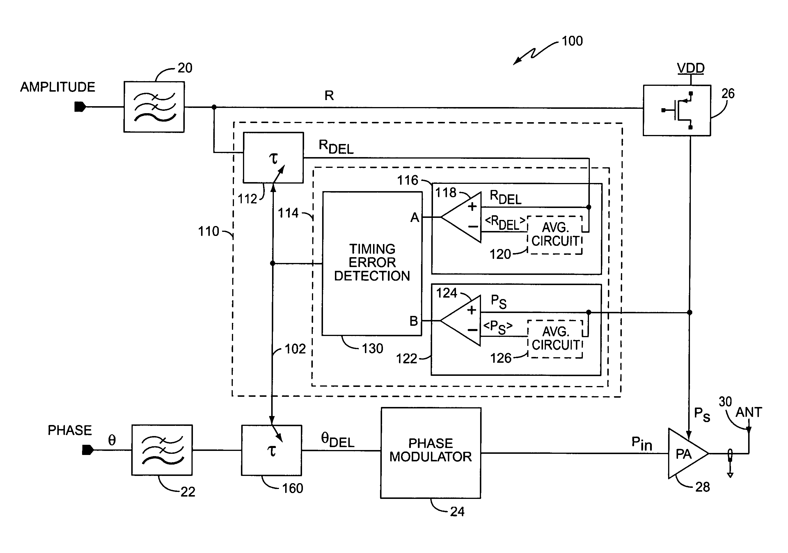
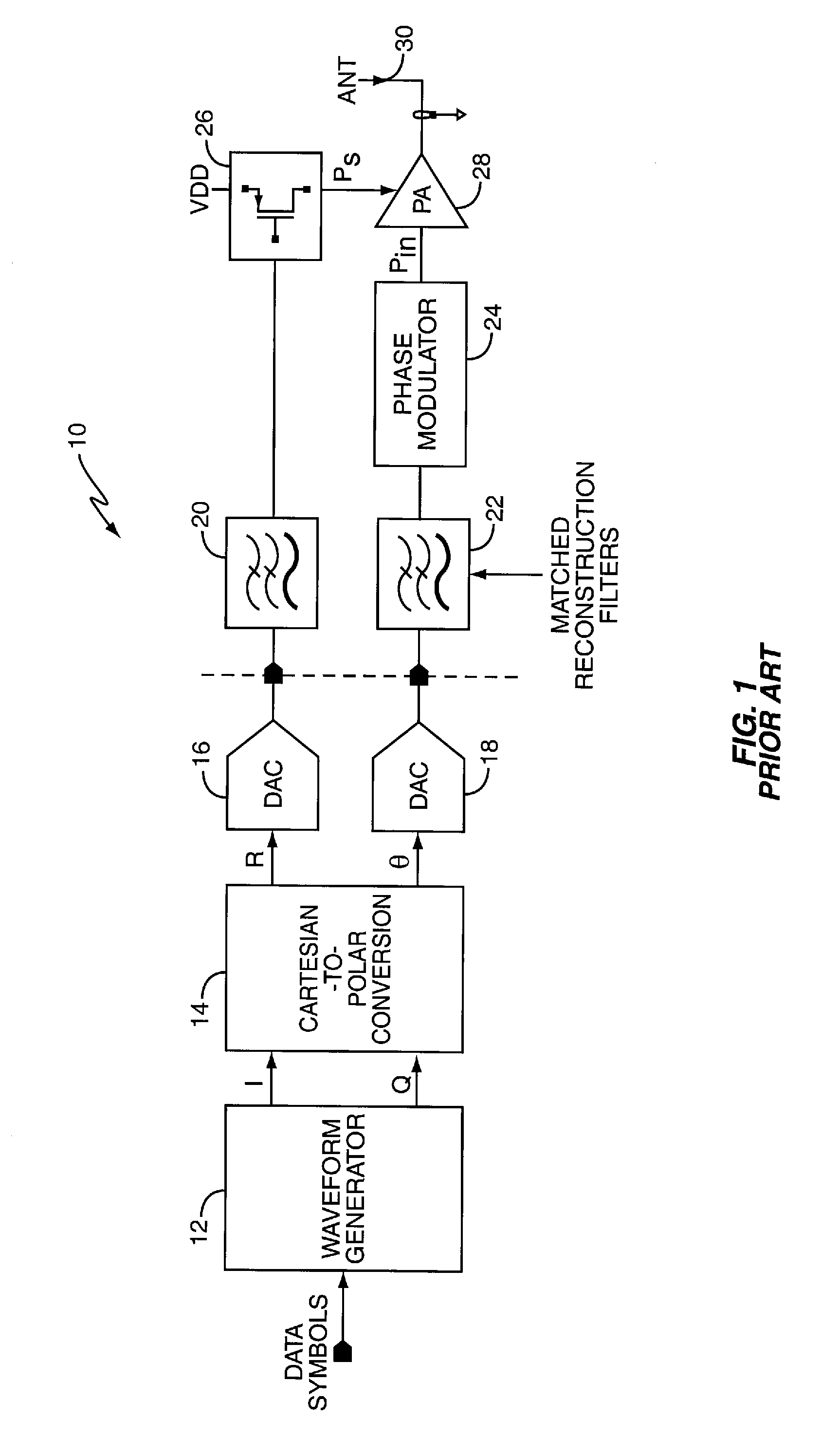
[0025]FIG. 1 illustrates a block diagram of a conventional polar modulation transmitter 10. Polar modulation transmitter 10 includes a waveform generator 12, Cartesian-to-Polar converter 14, digital-to-analog converters (DACs) 16, 18, filters 20, 22, phase modulator 24, regulator 26, power amplifier 28, and antenna 30. Waveform generator 12 generates in-phase (I) and quadrature-phase (Q) output signals responsive to the data input symbols. Cartesian-to-Polar converter 14 extracts the amplitude of the IQ signals according to Equation (2).
R=√{square root over (I2+Q2)} (2)
Cartesian-to-Polar converter 14 also generates a phase signal θ that represents the original IQ phase information with constant amplitude according to Equation (3).
[0026]θ=arctan(QI)(3)
It will be appreciated by those skilled in the art that phase signal θ may be separated into I and Q phase components, φI and φQ, where Equation (4) shows the relationship between θ and φI and φQ.
φI=cos(θ)
φQ=sin(θ) (4)
For simplicity...
PUM
 Abstract
Description
Claims
Application Information
 - R&D
- Intellectual Property
- Life Sciences
- Materials
- Tech Scout
- Unparalleled Data Quality
- Higher Quality Content
- 60% Fewer Hallucinations
Browse by: Latest US Patents, China's latest patents, Technical Efficacy Thesaurus, Application Domain, Technology Topic, Popular Technical Reports.
© 2025 PatSnap. All rights reserved.Legal|Privacy policy|Modern Slavery Act Transparency Statement|Sitemap|About US| Contact US: help@patsnap.com


