
Liquid crystal display projector

a liquid crystal display and projector technology, applied in the field of projection display devices, can solve the problems of additional limitations of lcd-lamp projectors, limitations imposed by the frame rate described for the crt, and additional time errors, so as to achieve precise and stable control of the projection system color temperature

Inactive Publication Date: 2008-04-15
BULLWINKEL PAUL +2
View PDF11 Cites 10 Cited by
  • Summary
  • Abstract
  • Description
  • Claims
  • Application Information

AI Technical Summary

Benefits of technology

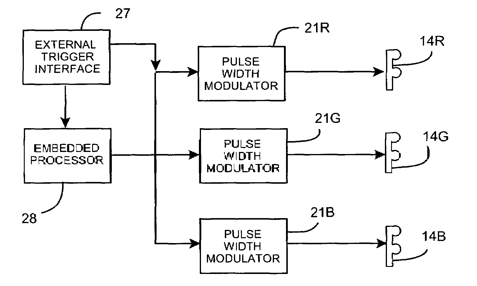
"The invention is a liquid crystal projector that uses Semi-conductor generated light arrays controlled by control electronics to provide precise and stable control of the projection system color temperature, adjust the color control over a wide range, maintain constant calibrated color temperature over an extended period of time, vary the brightness over a large range, maintain constant calibrated brightness over an extended period of time, precisely control the start time and duration of visual stimulus presentation, and provide an complete, fully developed stimulus immediately upon request. The invention also includes a method for providing a precise visual stimulus by pulsating the output of each light source at a pre-selected repetition rate."

Problems solved by technology

Even when these restrictions are observed and carefully controlled, additional time errors will be present.
For the conventional LCD-lamp projector the limitations imposed by the frame rate described for the CRT are still present.
But the LCD-lamp projector has additional limitations.
Because the conventional LCD has a relatively slow response time, frame rates are usually limited to 60 Hz.
The LCD lamp projector also can have other time errors.
The difficulty with color control in a CRT is two-fold: 1) the relationship of color intensity to electron beam intensity changes as the phosphors age; and 2) the electron beam intensity to brightness transfer function is non-linear.
The LCD lamp projector has a more limited ability to control color balance than even the CRT.
None of these factors can be adjusted during use to produce a different white point.
Brightness adjustment in a LCD projector is limited if it exists at all.
A problem with introducing conventional audio or video signals into an MRI apparatus is that the device is based upon the use of radio frequency which will disrupt signal modulation.

Method used


Image

  • Liquid crystal display projector
  • Liquid crystal display projector

Examples


Embodiment Construction

[0027]Although the invention will be described in terms of a specific embodiment, it will be readily apparent to those skilled in this art that various modifications, rearrangements, and substitutions can be made without departing from the spirit of the invention. The scope of the invention is defined by the claims appended hereto.

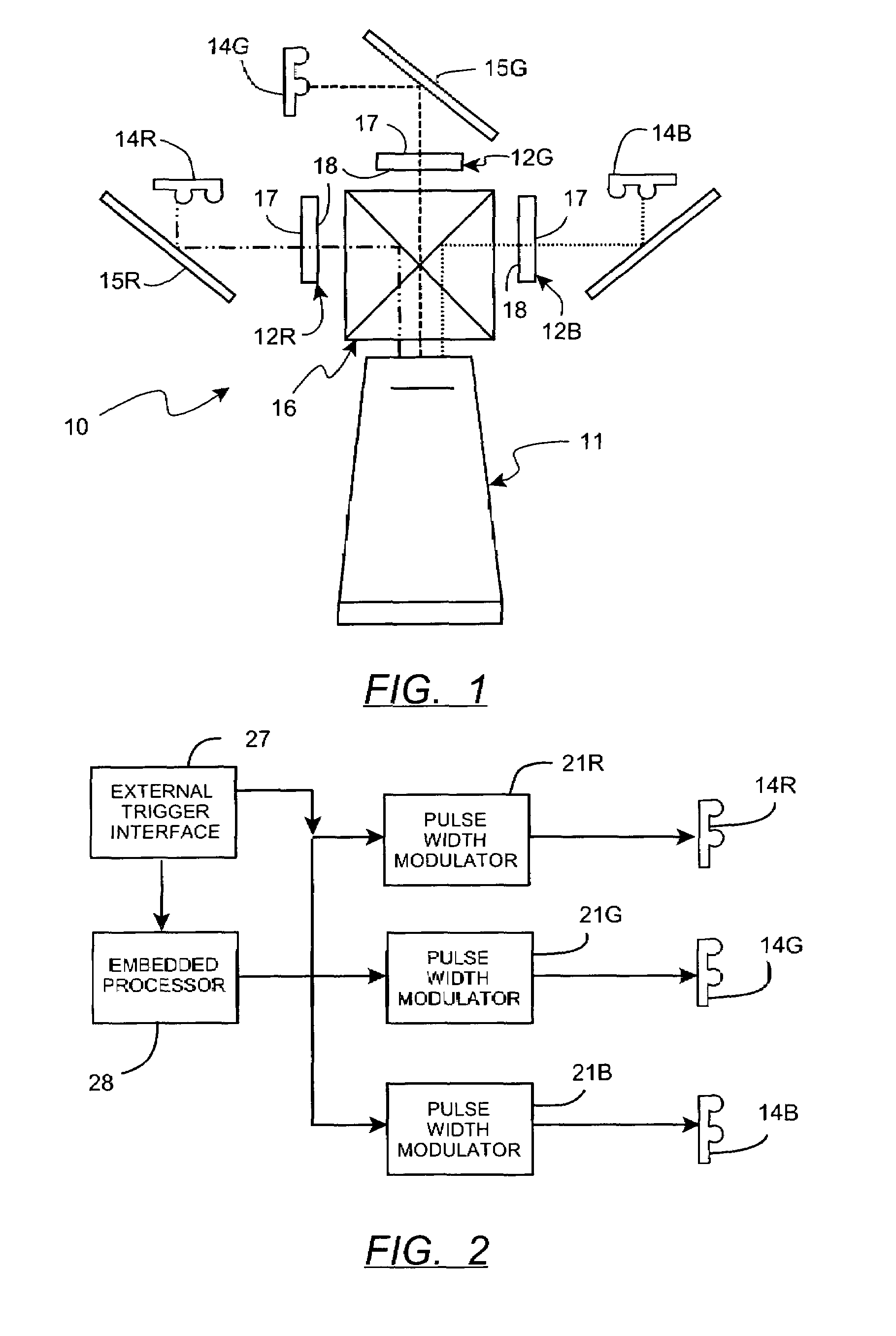
[0028]FIG. 1 illustrates the arrangement of elements of the projection system 10 of a liquid crystal projector unit. A projection lens assembly 11 is arranged at the front surface of the unit. The projection system 10 includes three liquid crystal display (LCD) panels denoted as 12R, 12G, and 12R which each include an incident light polarizing plate 17 on its incident surface and an image forming polarizing plate 18 on its output surface. The LCD panels 12R, 12G, and 12B respectively functions as a red image display for displaying a red image, a green image display for displaying a green image, and a blue image display panel for displaying a blue image. Th...


PUM

PropertyMeasurementUnit
color temperatureaaaaaaaaaa
frequencyaaaaaaaaaa
frequencyaaaaaaaaaa

Abstract

A liquid crystal projector comprises first, second and third liquid crystal panels having corresponding light sources, namely a red light source, a green light source, and a blue light source, wherein the red light source. The light sources are preferably Semi-conductor generated light arrays. The projector further includes a dichroic prism for superimposing the red, green and blue image displays, and a projection lens for projecting a full-color image beam formed by the dichroic prism. In order to control the intensity of the light sources, a pulse modulating means is coupled to each of the Semi-conductor generated light arrays, the pulse modulating means being operable to independently switch each of the light sources between an on state and an off state at a selectable repetition rate. An embedded processor is coupled to the pulse modulating means, wherein the processor is operable to control the selectable repetition rates hereby the relative brightness of each of the red, green and blue light sources can be independently and selectively varied. The invention also discloses a method for providing a precise visual stimulus for any environment.

Description

CROSS REFERENCE TO RELATED APPLICATIONS[0001]This application claims the benefit of the filing date of U.S. application No. 60 / 380,313 filed May 13, 2002, the contents of which are incorporated herein by reference.FIELD OF THE INVENTION[0002]This invention relates generally to the field of projection display devices, and more particularly to projection displays utilizing liquid crystal display (LCD) image generation devices to provide a precise visual stimulus as is required in the magnetic resonance imaging.BACKGROUND OF THE INVENTION[0003]It is important in the practice of functional magnetic resonance imaging (fMRI), as well as many other visual experiments, to provide visual stimulus having precisely controlled and well defined start times and presentation durations. In some instances, the diagnostic procedure performed with the MRI is used to evaluate a patient's response to specific visual stimuli. The operator sends a series of images to a screen which is seen by the patient ...

Claims


Application Information

Patent Timeline
Patent Type & Authority Patents(United States)
IPC IPC(8): G02F1/1345G09G3/34
CPCG09G3/3406G09G2320/0606G09G2320/0626G09G2320/064G09G2320/0666
Inventor BULLWINKEL, PAULSEAL, JIMKOPP, KEITH A.
Owner BULLWINKEL PAUL
Learn More