
Direct field acoustic testing system and method

a testing system and acoustic technology, applied in the field of vibration testing, can solve the problems of high vibration, mechanical stress and other extreme conditions, and many complex items such as satellites or other instruments are subject to high vibration, and achieve the effect of more stable and accurate control

Active Publication Date: 2015-08-18
LARKIN PAUL ALAN +2
View PDF6 Cites 6 Cited by
  • Summary
  • Abstract
  • Description
  • Claims
  • Application Information

AI Technical Summary

Benefits of technology

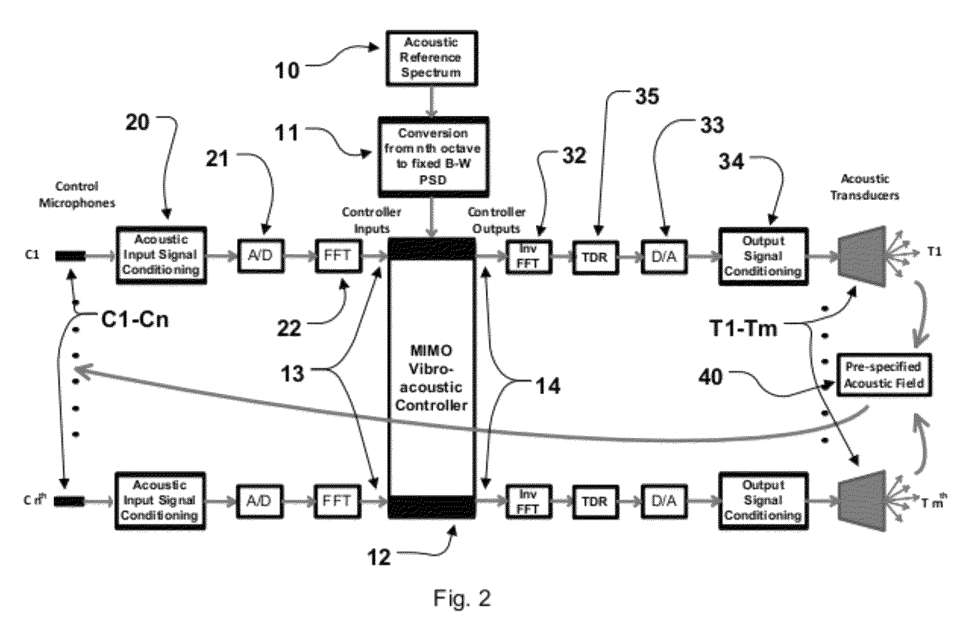
This patent describes a system for testing and controlling the sound in a space using microphones and speakers. The system uses a special converter to convert the sound signals to a more accurate and stable form, which can be used to control the output of the speakers. This allows for more precise and accurate control over the sound field in the space. The invention also includes a method for using multiple microphones to capture the sound and a way to control the sound in different areas of the space. Overall, the invention helps to create a better listening experience and provides better control over the sound in a space.

Problems solved by technology

Many complex items such as satellites or other instruments are subjected to high levels of vibration, mechanical stress and other extreme conditions during operation or as part of the process of being placed into service.
Failures may be difficult or impossible to repair after the object is placed in service and may be extremely costly.
However, a more complex control system involving multiple inputs and multiple outputs (MIMO) has also been used for the purpose of delivering specific test conditions to specific parts of the UUT.
Such mechanical testing is limited to relatively low frequencies and is unsuitable for evaluating the impact of high intensity acoustic vibrational fields on the UUT.
While these chambers are capable of very high acoustic levels, in excess of 150 db SPL, across a very broad acoustic bandwidth the acoustic field cannot be accurately controlled at higher frequencies, typically above 2 kHz, due to the nature of the transducers employed, and at low frequencies, typically below 50 Hz, where the low modal density of the chamber causes large spatial variations in the acoustic field.
In the case of satellites, rockets and other such valuable objects transportation is costly, time consuming and risky.
Additionally, the lack of control at high and low frequencies may result in over-testing and consequent damage to the UUT.
The usefulness of these tests was somewhat limited in that the acoustic field generated by the system exhibited substantial spatial variability and a high level of coherence meaning that it did not accurately simulate the desired reverberant field.
In addition, the limitations of then available commercial sound equipment made it difficult to reliably achieve high intensity acoustic fields at the desired levels.
Although no data on coherence is provided, there is no reason to believe that this system was any more successful in simulating a reverberant acoustic field than essentially identical systems previously used.
Even with such improvements, these prior art DFAT systems failed to produce adequate spatial uniformity or low enough coherence to be considered a reliable predictor of results from true reverberant field testing.

Method used


Image

  • Direct field acoustic testing system and method
  • Direct field acoustic testing system and method
  • Direct field acoustic testing system and method

Examples


Embodiment Construction

[0028]Embodiments hereof are now described with reference to the figures where like reference characters / numbers indicate identical or functionally similar elements. While specific configurations and arrangements are discussed, it should be understood that this is done for illustrative purposes only. A person skilled in the relevant art will recognize that other configurations and arrangements can be used without departing from the spirit and scope of the invention.

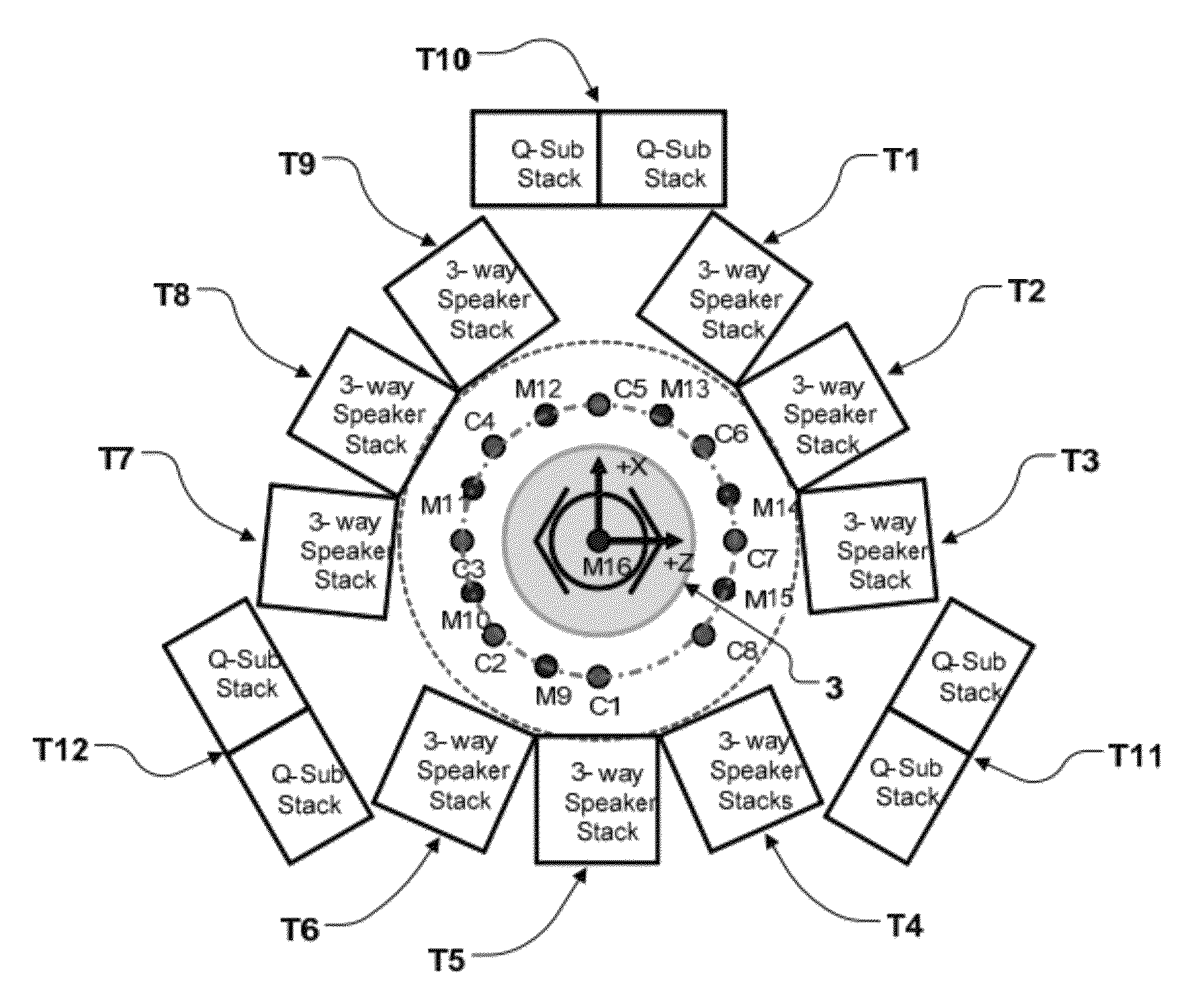
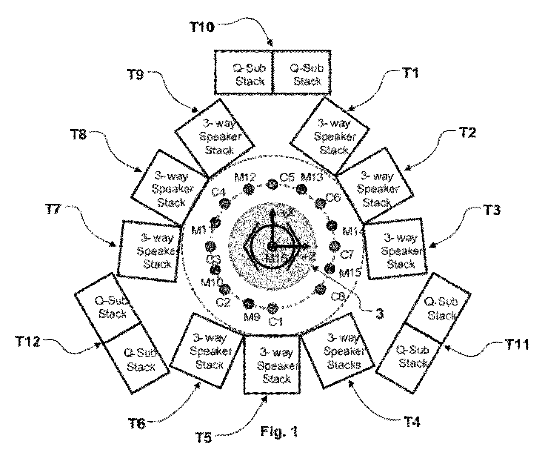
[0029]Referring to FIG. 1, an embodiment of a DFAT system includes a transducer array composed of electro-dynamic acoustic sources or transducers T1-T12 covering various frequency ranges arrayed around the unit-under test (UUT) 3 in a generally circular arrangement as shown. The transducer array in the embodiment shown is composed of twelve groups T1-T12 of eight transducers, of which nine groups T1-T9 are three-way electro-dynamic loudspeaker systems generally covering the frequency range above 100 Hz and three groups T1...


PUM

PropertyMeasurementUnit
frequenciesaaaaaaaaaa
frequencyaaaaaaaaaa

Abstract

A direct field acoustic testing system includes at least one control microphone, a controller operatively coupled to the control microphone such that the controller receives at least one input signal from the control microphone, and at least four acoustic transducers operatively coupled to the controller such that each transducer is separately controllable by the controller such that a separate output signal is received by each transducer from the controller. A setup is applied to each of the acoustical transducers. The acoustic output of each of the acoustical transducers is monitored using the at least one control microphone. The output signal of each control microphone with respect to each acoustical transducer is compared to a reference spectrum to create a matrix of error functions, and a corrected drive signal computed for each acoustical transducer is applied to the respective acoustical transducer.

Description

BACKGROUND OF THE INVENTION[0001]1. Field of the Invention[0002]The present invention relates generally to the field of vibration testing of objects such as satellites, instrumentation or any other object whose reliability in operation may be evaluated using high intensity vibration testing. Specifically, the present invention relates to the use of direct field acoustic systems to perform vibration testing and to control means to allow direct field acoustic systems to closely approximate the properties of a reverberant field.[0003]2. Background of the Invention[0004]Many complex items such as satellites or other instruments are subjected to high levels of vibration, mechanical stress and other extreme conditions during operation or as part of the process of being placed into service. Failures may be difficult or impossible to repair after the object is placed in service and may be extremely costly. As a result there have been many techniques developed to evaluate the reliability of ...

Claims


Application Information

Patent Timeline
Patent Type & Authority Patents(United States)
IPC IPC(8): G01N29/04G01M7/00
CPCG01M7/00G01N29/04
Inventor LARKIN, PAUL ALANGOLDSTEIN, ROBERT TURKUNDERWOOD, MARCOS A.
Owner LARKIN PAUL ALAN
Learn More