Storage network switch

a network switch and storage technology, applied in the direction of program control, multi-programming arrangements, instruments, etc., can solve the problems of increasing the amount of data processing and the befitting cost of exchanging load information, and achieving the effect of reducing the burden on the host computer, and reducing the load on the disk storage system

Inactive Publication Date: 2008-04-08
HITACHI LTD
View PDF20 Cites 28 Cited by
  • Summary
  • Abstract
  • Description
  • Claims
  • Application Information

AI Technical Summary

Benefits of technology

[0010]The problem to be solved by the present invention may be overcome by having a load measuring block in the storage network switch used for connecting a plurality of host computers with a plurality of disk storage systems. The storage network switch is a routing device which handles and relays communication between computers and storages, the amount of communication routed thereby namely, the traffic may be counted for example as the number of input and output (I / O) commands arriving from hosts so as to monitor and measure the load on the disk storage systems faster, to thereby enable the load balancing to be implemented effectively. The burden on host computers will be significantly decreased since hosts require not to exchange information on the status of accessing each of disk storage systems.
[0011]There may be cases in which the utilization of the processing power of host computers for commanding data movement is more effective, when a storage network switch executes the load balancing by replacement of data, namely, data movement based on the result of measured load. In such a case the load measuring block will need to inform host computers of the load information of monitored measurements in order to direct host computers to issue data movement commands.
[0012]There may also be cases in which, by pre-configuring a threshold for the varying load, an overloaded condition can be determined if the load exceeds the threshold and data movement can be effectively performed when the overload is detected. In such a case the storage network switch will require issuing data movement command by notifying the load information to the host computers. The hosts upon reception of the requirement will generate a data movement command based on thus received load information to send it to the storage network switch.

Problems solved by technology

The longer the response time, the longer the load measuring, therefore the effective load balancing may become difficult.
In addition, the increased amount of data processing requires a befitting cost for exchanging load information and data movement.

Method used


Image

  • Storage network switch
  • Storage network switch
  • Storage network switch

Examples


Embodiment Construction

[0029]A detailed description of some preferred embodiments embodying the storage network switch in accordance with the present invention will now be given referring to the accompanying drawings.

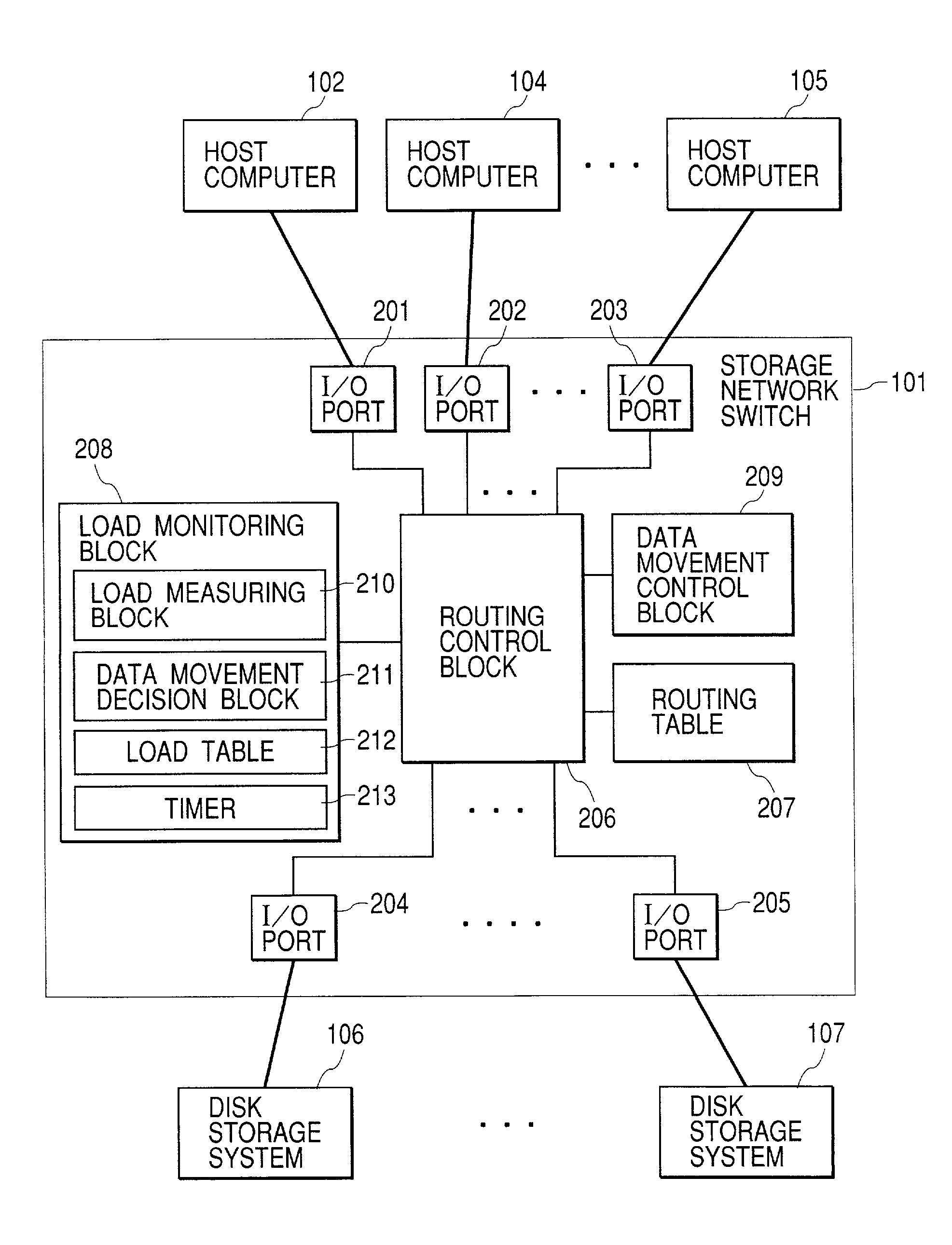
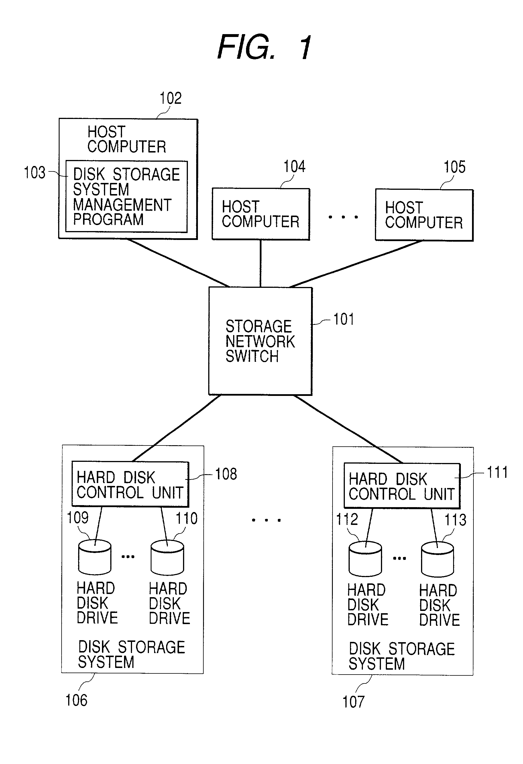
[0030]A typical example of computer system with a storage network switch in accordance with the present invention is shown in FIG. 1. The computer system shown FIG. 1 comprises a storage network switch 101, host computers 102, 104, and 105, disk storage systems 106 and 107. The host computers 102, 104, and 105 and disk storage systems 106 and 107 are connected to storage network switch 101. The I / O commands and output data from the host computers 102, 104, and 105 will be transferred to the disk storage systems 106 and 107 via the storage network switch 101. The data sent from the disk storage systems 106 and 107 will be transferred to the host computers 102, 104, and 105 via the storage network switch 101.

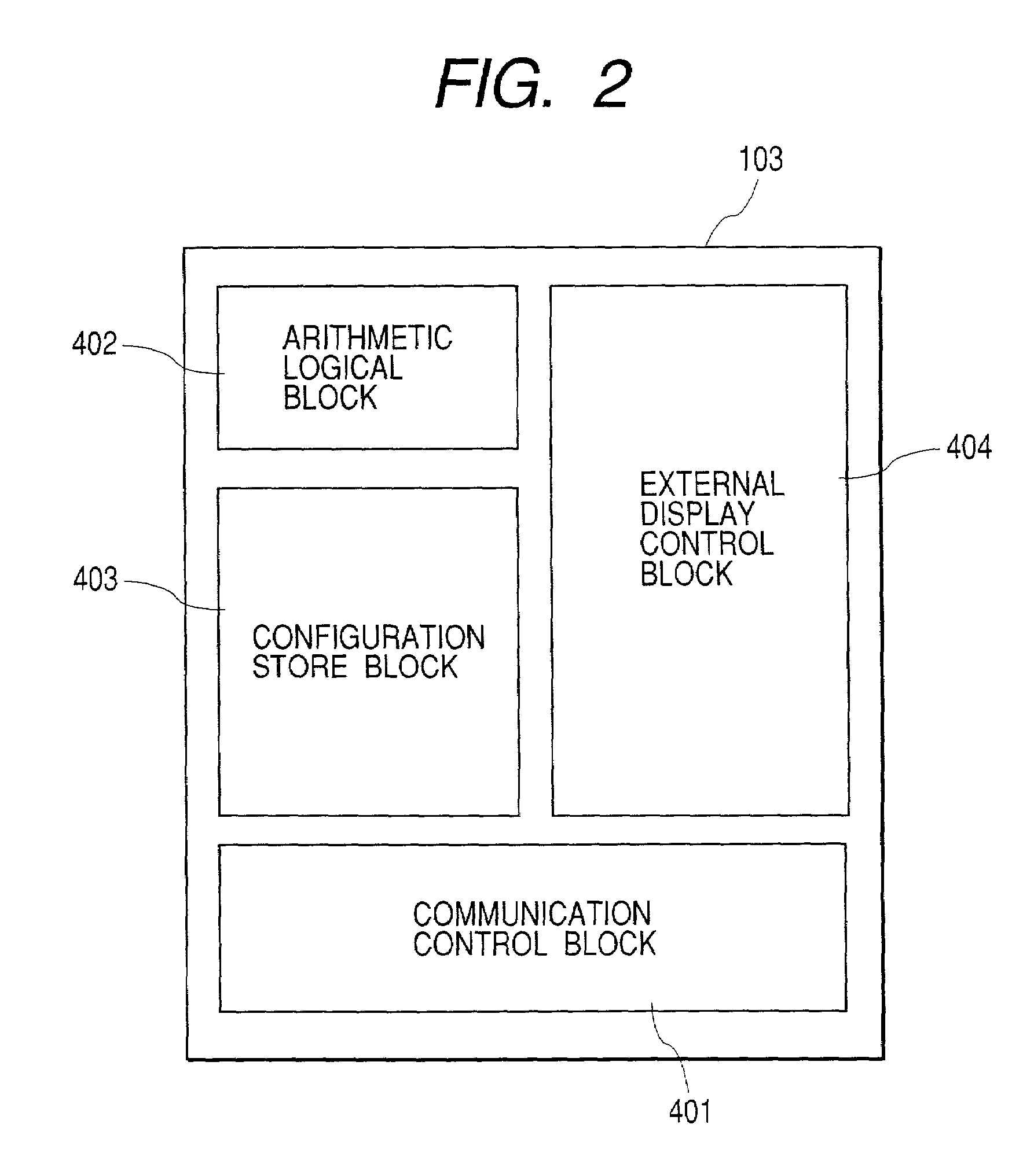
[0031]The host computer 102 may have a disk storage system management program 103 for s...


PUM


Abstract

The present invention provides a storage network switch suitable for effective load balancing of a plurality of disk storage systems along with the mitigated burden of the host computer. The storage network switch for connecting a plurality of host computers to a plurality of disk storage systems has a load measuring means, and a data movement facility if required.

Description

BACKGROUND OF THE INVENTION[0001]The present invention relates to a technology for balancing loads among a plurality of disk storage systems and more particularly to a storage network switch for networking a plurality of computers and a plurality of disk storage systems receiving the load balancing[0002]Most common design of computer systems to the date has been constituted of one host computer with a plurality of disk storage systems. To distribute load balancing among disk storages in such a system, the host computer is in general in charge of balancing. More specifically, in most cases, a program on the host monitors the load of disk storages, and in order to move data for load balancing, a user operates the computer, according to the monitored measurements to manually instruct the data movement.[0003]For example, a typical process of data movement is disclosed in “SPARC & Solaris: performance tuning” by Adrian Cockcroft, Sun Microsystems Japan, Inc. Ed., pp 87 to pp 95, publishe...

Claims


Application Information

Patent Timeline
Patent Type & Authority Patents(United States)
IPC IPC(8): G06F11/34G06F9/50G06F3/06H04L29/06H04L29/08
CPCG06F3/0613G06F3/0647G06F3/067H04L29/06H04L67/1008H04L67/1012G06F2206/1012H04L2029/06054H04L67/1002H04L67/10015H04L67/1001H04L9/40
Inventor HASHIMOTO, AKIYOSHI
Owner HITACHI LTD
Why Eureka
Try Eureka