Arrangement structure of heat exchanger in condensing gas boiler

a technology of arrangement structure and condensing gas boiler, which is applied in the direction of heating types, lighting and heating apparatus, and steam generation using hot heat carriers, etc., can solve the problems of corroding internal heat exchangers, low thermal efficiency, and inability to compact condensing gas boilers, and achieve the effect of compact boilers

Active Publication Date: 2008-04-08
KYUNGDONG NAVIEN
View PDF2 Cites 5 Cited by
  • Summary
  • Abstract
  • Description
  • Claims
  • Application Information

AI Technical Summary

Benefits of technology

[0011]To solve the above problems, it is an object of the present invention to provide an arrangement structure of heat exchangers in a condensing gas boiler which maximizes a heat transfer area and makes present heat and condensing conditions to thereby improve a heat exchanging efficiency, and to then accomplish compactness and corrosion resistance of the boiler.
[0020]An exhaust gas exit is integrally penetratively formed on the upper portion of the casing, to thus accomplish compactness of the boiler.

Problems solved by technology

However, an internal heat exchanger is corroded due to acid moisture generated at the time of a condensation process, and sulfuric oxide, nitric oxide, and combustion heat included in exhaust gas.
Although aluminum or stainless steel has a good corrosion-resistant property, its thermal efficiency is low.
As a result, the condensing gas boiler cannot be compact.
As a result, a heat exchanging efficiency is reduced.

Method used


Image

  • Arrangement structure of heat exchanger in condensing gas boiler
  • Arrangement structure of heat exchanger in condensing gas boiler
  • Arrangement structure of heat exchanger in condensing gas boiler

Examples


Embodiment Construction

[0030]Preferred embodiments of the present invention will be described with reference to the accompanying drawings. The same or like elements are assigned with the same or like reference numerals.

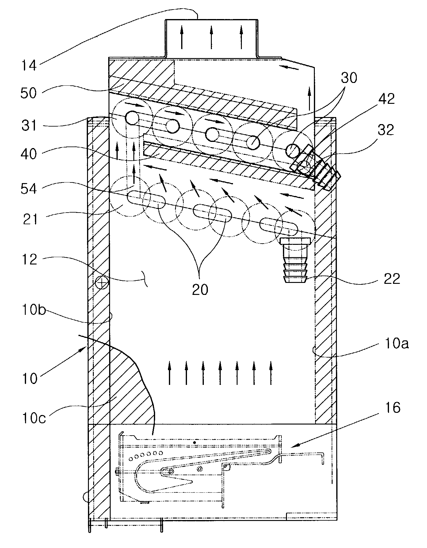
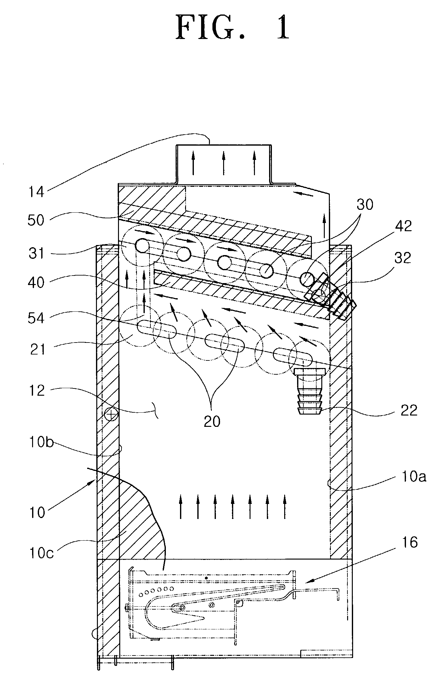
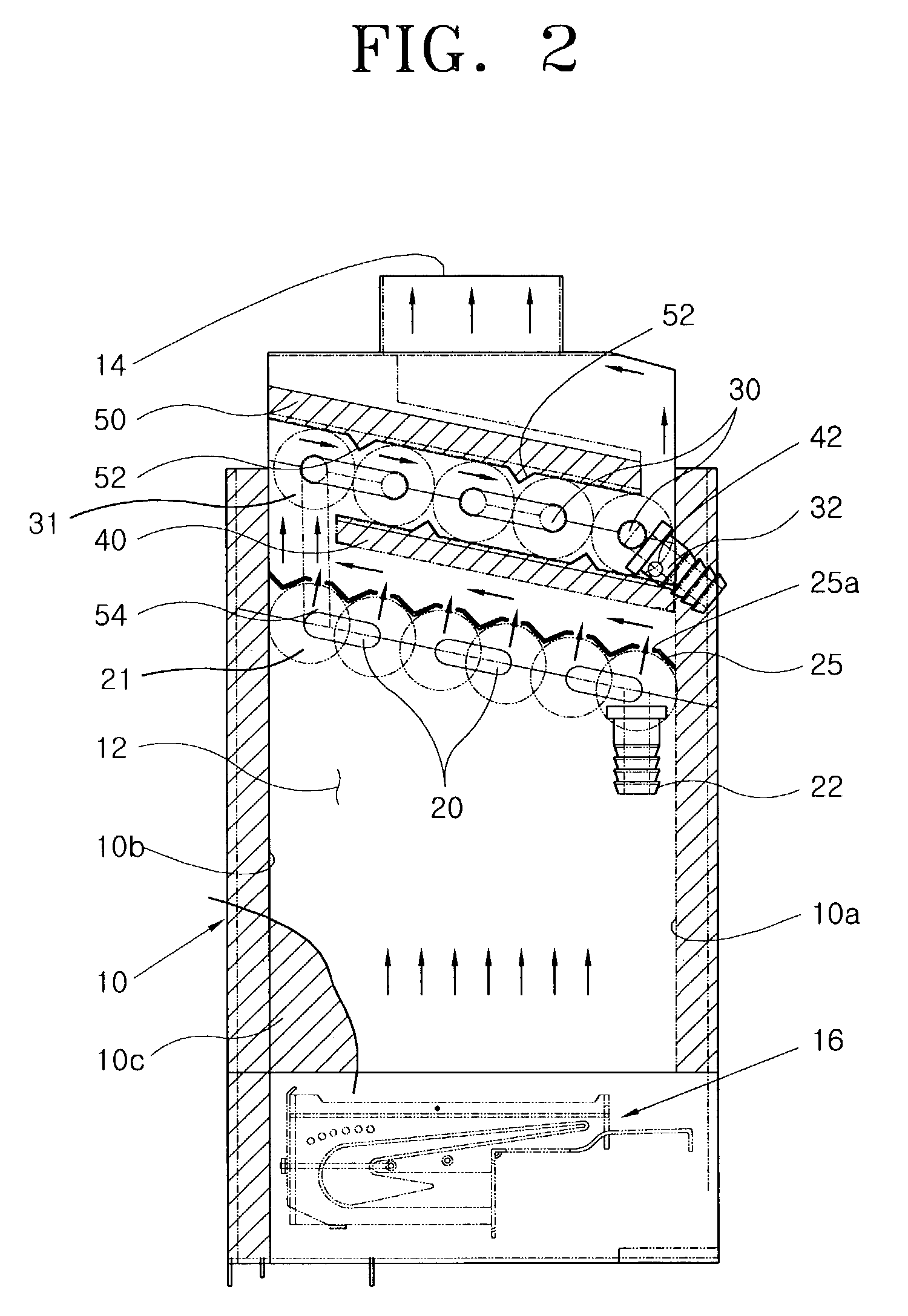
[0031]As shown in FIGS. 1 through 4, a condensing gas boiler according to the present invention includes a casing 10 which forms an outer case and includes a combustion chamber 12 therein.

[0032]A heat isolation material 10c is filled in the side walls of the casing 10, in order to suppress heat in the combustion chamber 12 from being irradiated to thus heighten a combustion efficiency. An exhaust gas exit 14 is formed on the upper portion of the casing 10. In this embodiment, the exhaust gas exit 14 is integrally formed on the upper portion of the casing 10 toward a latent heat exchanger 30 to be described later, without a separate exhaust gas guiding plate (not shown). Thus, the present invention can achieve compactness of the boiler and save the manufacturing cost.

[0033]A gas burner 16 is...


PUM


Abstract

An arrangement structure of heat exchangers in a condensing gas boiler is provided, which includes a casing provided with a combustion chamber therein, and a gas burner provided in the lower portion of the combustion chamber. The arrangement structure of heat exchangers in a condensing gas boiler includes: a present heat exchanger slantly arranged with a predetermined slope with respect to a horizontal axis on a transverse cross-section in the casing; a latent heat exchanger disposed in parallel with the present heat exchanger, in the same area as that of the present heat exchanger in the upper portion of the present heat exchanger; a condensed waterspout provided in parallel with between the present heat exchanger and the latent heat exchanger, whose one end contacts one of the inner wall surfaces of the casing and whose other end is disposed spaced from the other of the inner wall surfaces thereof; and an exhaust gas flowing plate provided in parallel with the outer wall of the latent heat exchanger, whose one end is spaced from one of the inner wall surfaces of the casing and whose other end contacts the other of the inner wall surfaces of the casing in order to induce condensed water and exhaust gas to flow in an identical direction. Thus, the heat transfer area is maximized, and present heat and condensing conditions are made to improve a heat exchanging efficiency, and to accomplish compactness and corrosion resistance of the boiler.

Description

BACKGROUND OF THE INVENTION[0001]1. Field of the Invention[0002]The present invention relates to an arrangement structure of heat exchangers in a condensing gas boiler, and more particularly, to an arrangement structure of heat exchangers in a condensing gas boiler which maximizes a heat transfer area and makes present heat and condensing conditions, to thereby improve a heat exchanging efficiency, and to then accomplish compactness and corrosion resistance of the boiler.[0003]2. Description of the Related Art[0004]A boiler for use in general homes and buildings is used for heating water and supplying hot water, which is divided into a fuel oil boiler and a fuel gas boiler, according to a type of a fuel used.[0005]When a fuel oil boiler and a fuel gas boiler each having an identical capacity are compared with each other, the former is cheaper than the latter in view of its purchasing price, but the latter is more economic than the former in view of an amount of fuel consumed.[0006]H...

Claims


Application Information

Patent Timeline
IPC IPC(8): F22B1/18F24H1/14F24H1/40F24H8/00F24H9/00F28F1/26F28F21/08
CPCF24H1/40F24H8/006F24H9/0026Y02B30/00
Inventor JUNG, YONG HYENHUR, WOO SUK
Owner KYUNGDONG NAVIEN
Why Eureka
Try Eureka