
Zoom lens and imaging apparatus

a zoom lens and imaging apparatus technology, applied in the field of zoom lenses and imaging apparatuses, can solve the problem of large blur in images, and achieve the effect of high optical performan

Inactive Publication Date: 2009-07-07
SONY CORP
View PDF10 Cites 4 Cited by
  • Summary
  • Abstract
  • Description
  • Claims
  • Application Information

AI Technical Summary

Benefits of technology

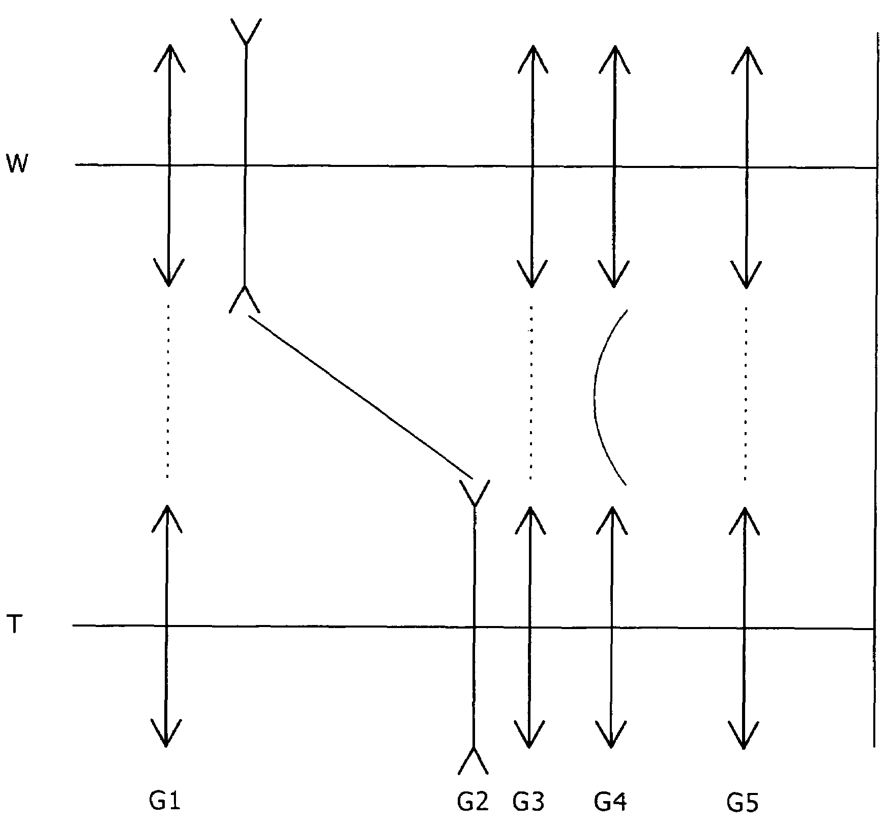
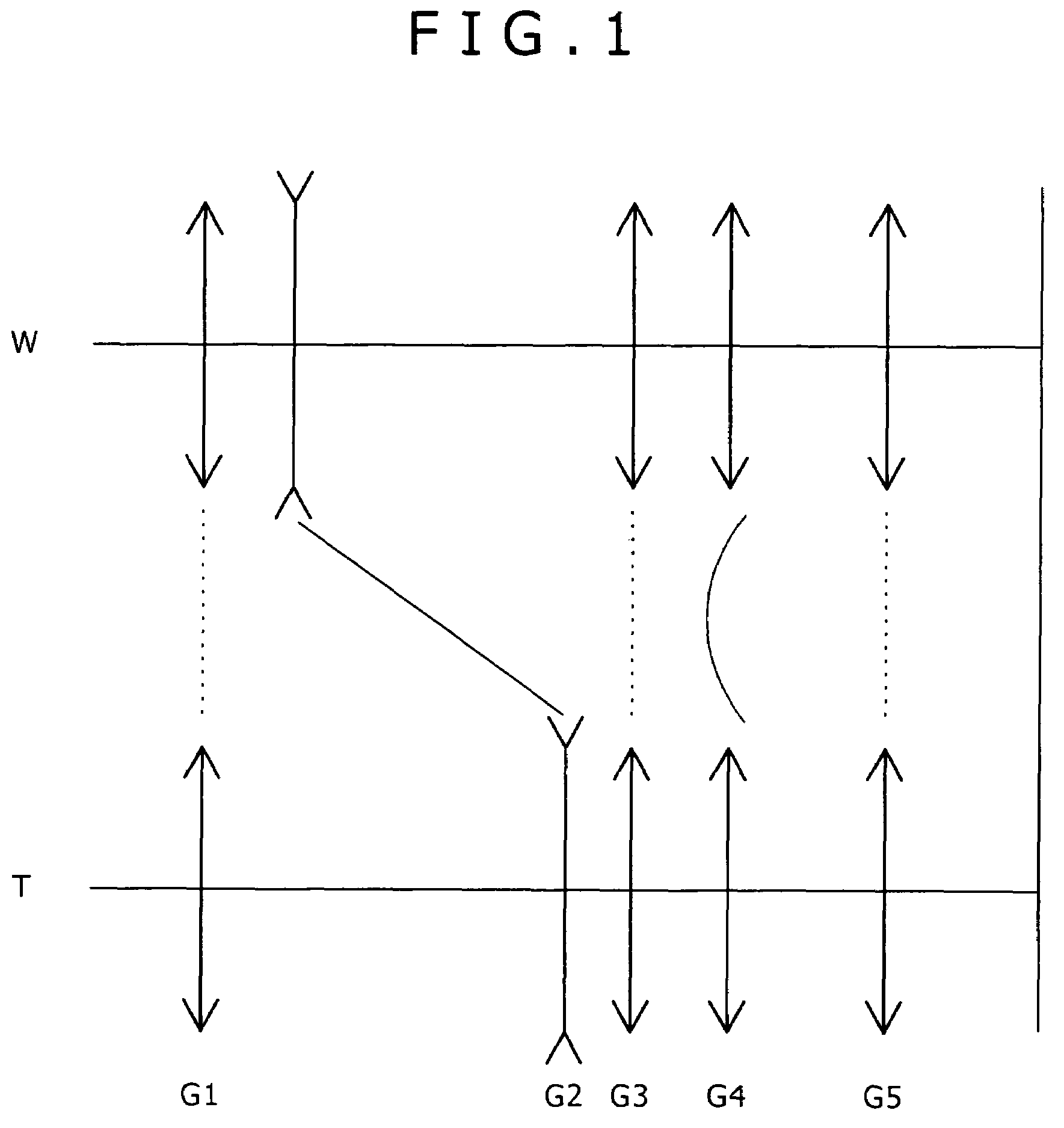
[0020]Accordingly, in the present invention, with the fifth lens group arranged, the number of lenses constituting the fourth lens group, which is movable, is reduced, and the weight thereof is thereby reduced. Consequently, the structure of a mechanism for driving the fourth lens group is simplified, thereby enabling the lens system to be compact.
[0021]In addition, when mounting a motion blur compensation mechanism, a mechanism for shifting the lens along the direction substantially perpendicular to the optical axis does not interfere with, for example, a lens driving mechanism for zooming and focusing and an aperture diaphragm opening / closing mechanism. Consequently, the size of a lens barrel, and especially, the size in the radial direction can be reduced, and compactness can be accomplished.
[0022]Since conditional equation (1) is satisfied, a drive mechanism for shifting the positive sub lens group of the fifth lens group can be configured to be compact. In addition, the total lens length can be reduced, and the eccentric coma occurring in the central portion of the screen can be prevented from being excessively increased during the shift event (“image shift”, hereafter) of the positive sub lens group.
[0025]The invention defined in some other embodiments satisfies conditional equation (4) given as −5<C5p·ft<−2, where C5p is a curvature (reciprocal of a radius of the curvature) of the most-image-side lens surface of the positive sub lens group disposed in the fifth lens group. Accordingly, the various aberrations occurring in the positive sub lens group of the fifth lens group can be sufficiently compensated for, and high optical performance can be obtained also during the image shift.

Problems solved by technology

However, in an optical system with a high zoom ratio, since the angle of viewing is narrowed in a telephoto end mode, even a small motion blur causes the occurrence of a large blur in the image.
In the conventional motion blur compensation optical systems, the lens group disposed near the aperture diaphragm is shifted, such that interferences tend to occur among a drive mechanism of causing the shifting, a mechanism of opening and closing the aperture diaphragm, and a mechanism of moving the respective lens in the event of, for example, zooming or focusing, so that a lens barrel has to be enlarged in the radial direction.

Method used


Image

  • Zoom lens and imaging apparatus
  • Zoom lens and imaging apparatus
  • Zoom lens and imaging apparatus

Examples


first embodiment

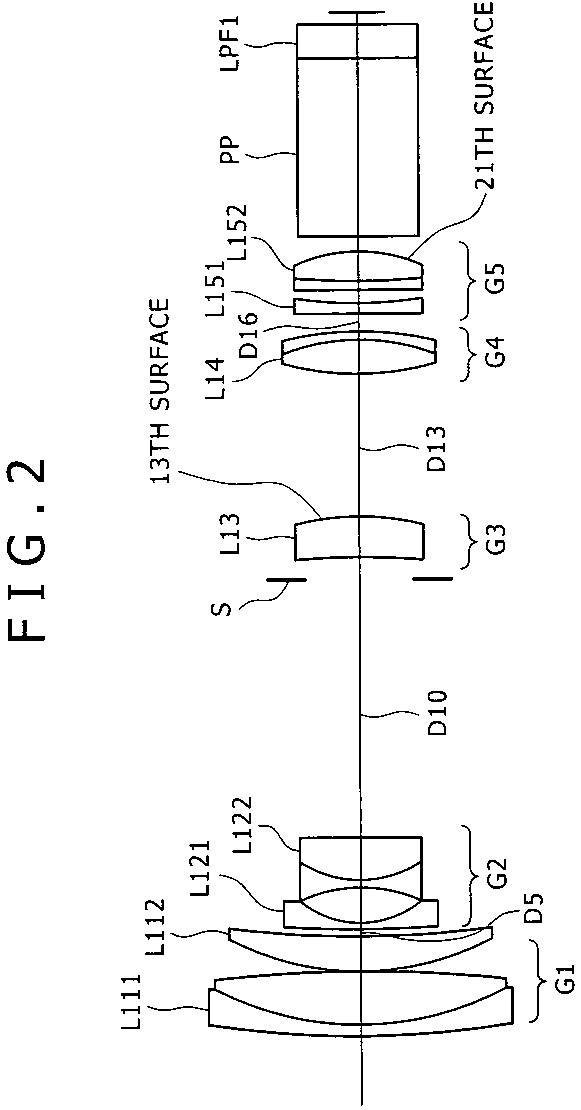
[0086]FIG. 2 shows a lens configuration according to the present inventive zoom lens, in which a first lens group G1 is formed of a cemented lens L111 of a meniscus-shaped negative lens with the convex surface facing the object side, and a positive lens L112 with the convex surface facing the object side; a second lens group G2 is formed of a negative lens L121 with the concave surface facing the image side, and a cemented lens L122 of a both-side concave shaped negative lens and a positive lens with the convex surface facing the object side; a third lens group G3 is formed of a positive meniscus lens L13; a fourth lens group G4 is formed of a cemented positive lens L14 of a both-side convex lens and a meniscus-shaped negative lens with the concave surface facing the object side; and a fifth lens group G5 is formed of a negative lens L151 with the concave surface facing the image side, and a cemented positive lens L152 of a both-side convex lens and a meniscus-shaped negative lens w...

second embodiment

[0101]FIG. 9 shows the lens configuration of the present inventive zoom lens, in which a first lens group G1 is formed of a cemented lens L211 of a meniscus-shaped negative lens with the convex surface facing the object side, and a positive lens L212 with the convex surface facing the object side; a second lens group G2 is formed of a negative lens L221 with the concave surface facing the image side, and a cemented lens L222 of a both-side concave shaped negative lens and a positive lens with the convex surface facing the object side; a third lens group G3 is formed of a negative meniscus lens L231 and a both-side convex lens L232; a fourth lens group G4 is formed of a cemented positive lens L24 of a both-side convex lens and a meniscus-shaped negative lens with the concave surface facing the object side; and a fifth lens group G5 is formed of a both-side concave lens L251 and a both-side convex lens L252.

[0102]In the second embodiment, an aperture diaphragm S is disposed on the obj...

third embodiment

[0116]FIG. 16 shows the lens configuration of the present inventive zoom lens, in which a first lens group G1 is formed of a cemented lens L311 of a meniscus-shaped negative lens with the convex surface facing the object side, and a positive lens L312 with the convex surface facing the object side; a second lens group G2 is formed of a negative lens L321 with the concave surface facing the image side, and a cemented lens L322 of a both-side concave shaped negative lens and a positive lens with the convex surface facing the object side; a third lens group G3 is formed of a negative meniscus lens L331 and a both-side convex lens L332; a fourth lens group G4 is formed of a cemented positive lens L34 of a both-side convex lens and a meniscus-shaped negative lens with the concave surface facing the object side; and a fifth lens group G5 is formed of a both-side concave lens L351 and a both-side convex lens L352.

[0117]In the third embodiment, an aperture diaphragm S is disposed on the obj...


PUM


Abstract

An electrode for an extra-high pressure discharge lamp, comprises large diameter portion which is symmetrical with respect to an axis of the electrode, a small diameter portion connected to the large diameter portion, wherein the large diameter portion is connected to the small diameter portion through an outer surface portion of the electrode, wherein a stripe lines like pattern portion, extending along an electrode axis direction, is formed on a portion to be brought in contact with glass of a lamp, and wherein unevenness is formed over an entire circumference of the electrode in a cross sectional view of the electrode taken along a direction perpendicular to the electrode axis direction.

Description

TECHNICAL FIELD[0001]The present invention relates to a zoom lens and an imaging apparatus, and more specifically, to an imaging apparatus device suited for use with cameras, such as video cameras or digital still cameras, that receive light from an imaging device. The invention also relates to a zoom lens and an imaging apparatus that use the zoom lens suited for motion blur compensation.BACKGROUND ART[0002]Conventionally, methods are known that convert an image of an object (object image) formed on an imaging device plane by using the imaging device that utilizes photoelectric transducers, such as CCDs (charge coupled devices) and CMOSs (complementary metal-oxide semiconductors), and that thereby record the image.[0003]With advancements in microprocessing technology, there have been implemented, for example, processing rate enhancements of central processing units (CPUs) and higher level integration of storage mediums, thereby enabling high speed processing of a large volume of im...

Claims


Application Information

Patent Timeline
Patent Type & Authority Patents(United States)
IPC IPC(8): G02B15/14G02B27/64G03B17/00
CPCG02B27/646G02B15/173G02B15/145129G02B13/009G02B3/0087G03B17/12H04N23/55
Inventor OHTAKE, MOTOYUKI
Owner SONY CORP
Learn More