
Power supply unit with perforated housing

a technology of power supply unit and perforated housing, which is applied in the direction of power supply for data processing, instruments, cooling/ventilation/heating modification, etc., can solve the problems of reducing the effectiveness of air channelling over heat-generating internal components of the psu to atmosphere, and acceptable disadvantages, so as to reduce the effectiveness of air channelling and reduce the formation of hotspots , the effect of reducing the flow rate fan

Inactive Publication Date: 2008-04-01
HIGH PERFORMANCE GRP
View PDF14 Cites 7 Cited by
  • Summary
  • Abstract
  • Description
  • Claims
  • Application Information

AI Technical Summary

Benefits of technology

"The invention is a power supply unit for a computing device that includes a housing with at least one fan and at least one hole in each of the upper, lower, and first to fourth side walls of the housing. The holes allow air to flow through the housing and cool the internal components of the power supply unit. The use of holes reduces the need for high-flow fans, which saves cost and reduces noise. The holes are positioned close to the fan and are preferably circular in shape, with a distance between the centers of adjacent holes ranging from 1.1 to 2 times the maximum width of the first hole. The holes can be formed by perforating a metal sheet. The technical effect of the invention is to provide a power supply unit with improved cooling efficiency and reduced noise levels."

Problems solved by technology

This is disadvantageous in so far as it reduces the effectiveness of the channelling of air over heat-generating internal components of the PSU to atmosphere.
However, the inventors consider this to be an acceptable disadvantage in light of the function of the holes to remove hotspots within the PSU housing.

Method used


Image

  • Power supply unit with perforated housing
  • Power supply unit with perforated housing
  • Power supply unit with perforated housing

Examples


Embodiment Construction

[0045]In FIGS. 1 to 5, like reference numerals refer to like elements.

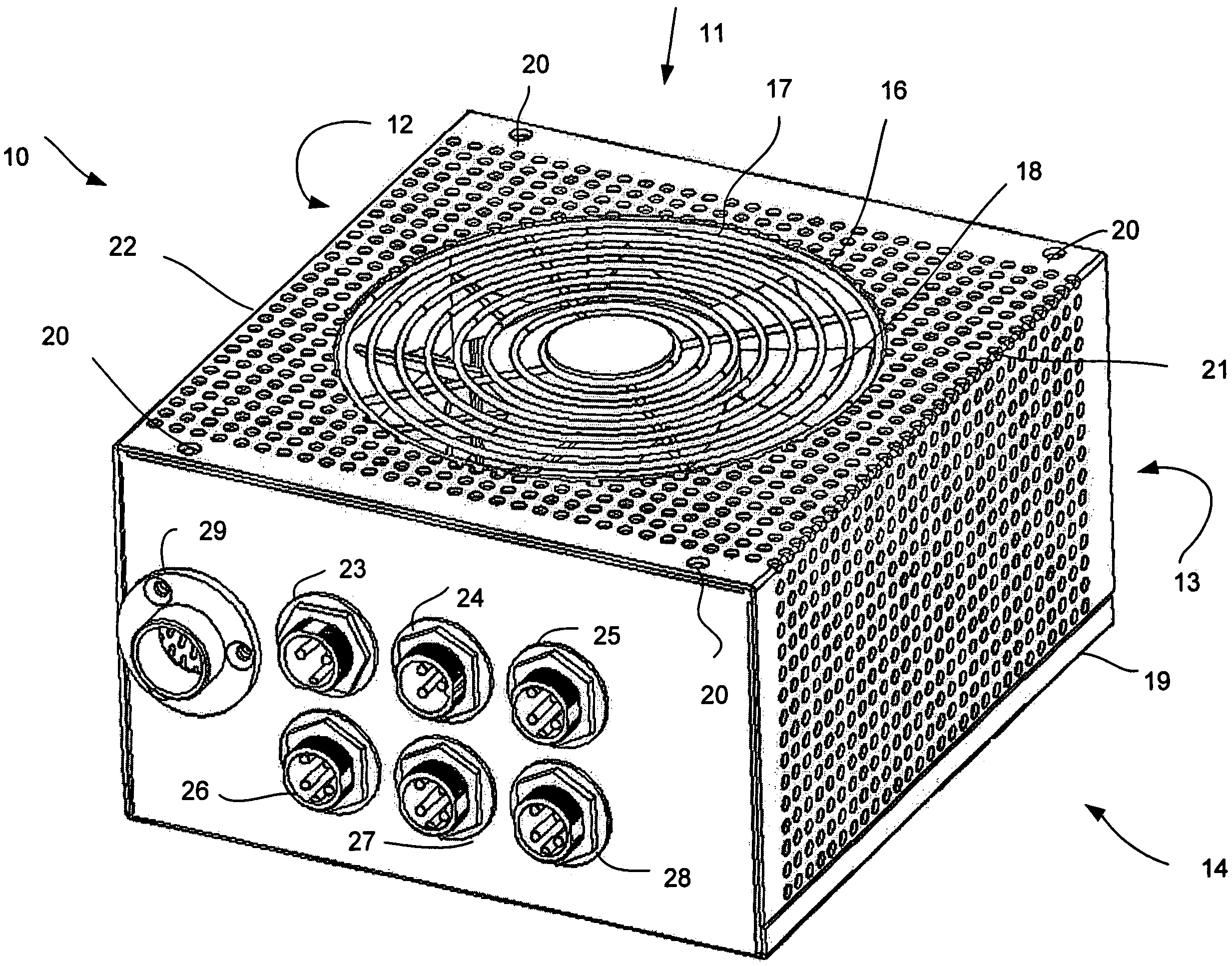
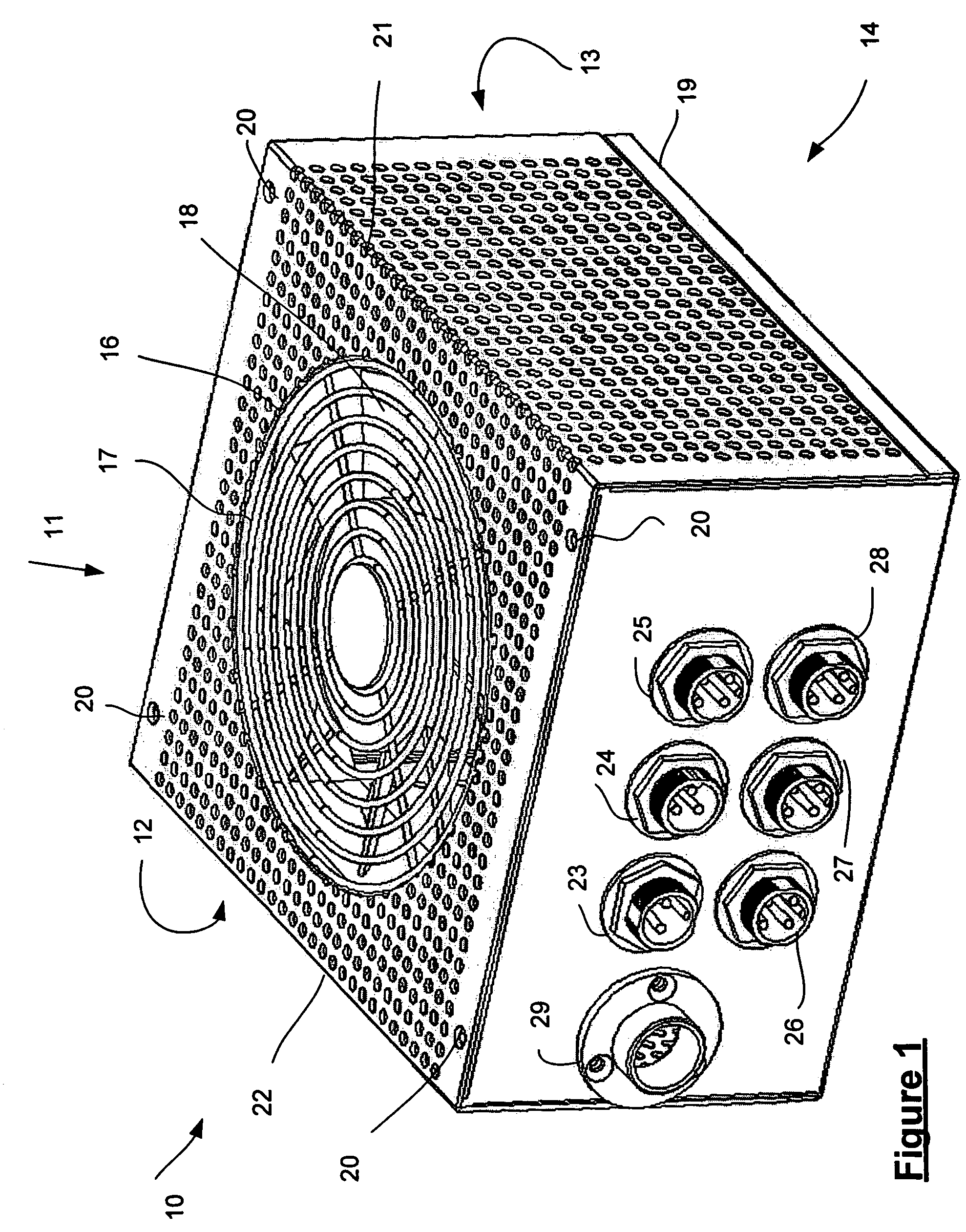
[0046]Referring to FIG. 1, a power supply unit (PSU) 10 according to the invention is generally cuboid in shape and has a top or upper wall 11, a right side wall 12 (not visible in FIG. 1), a front wall 13 (not visible in FIG. 1), a left side wall 14, a rear wall 15 and a bottom wall (not shown). The rear and front walls 13, 15 can be referred to as side walls since they are at the side of the PSU 10. The walls 11-15 define an internal volume of the PSU 10.

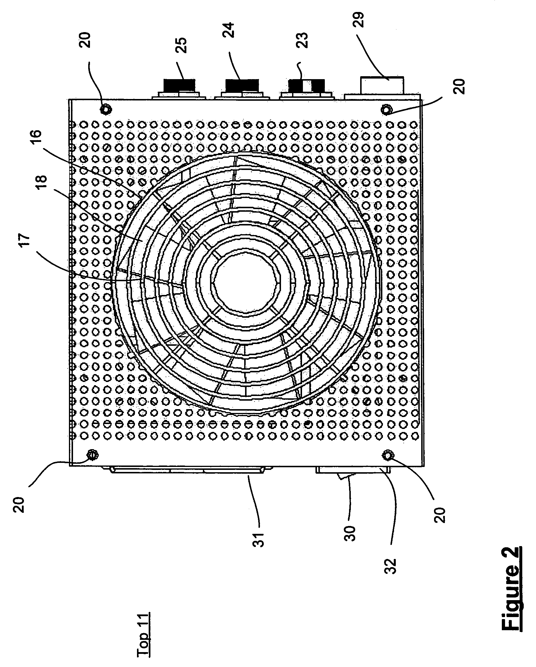
[0047]The upper wall 11 has formed therein a circular aperture 16, which constitutes a fan aperture. Supported on the upper wall 11 of the PSU 10 is a fan aperture cover 17. This is the same shape and size as the fan aperture 16, and is screwed to the upper wall 11. The fan aperture cover 17 comprises a number of circular metal. components connected together by radial metal spokes. The fan aperture cover 17 prevents the ingress of a user's fingers through the fa...


PUM


Abstract

A power supply unit (PSU) has walls which define an internal volume of the PSU. A metal sheet forming left and right side walls and an upper wall is provided with plural perforations on each of those walls. The perforations are circular in shape, and formed in a regular grid pattern. The perforations are formed by punching the metal sheet before it is bent into shape. The perforations in the housing of the PSU allow hotspots to be carried through the walls of the housing of the PSU, following which the hotspots are unable to damage internal components of the PSU. This allows the use of reduced flow rate fans.

Description

FIELD OF THE INVENTION[0001]This invention relates to a power supply unit.BACKGROUND OF THE INVENTION[0002]It is well known to provide computing devices such as personal computers (PCs), servers, media centers and the like with power supply units (PSUs). A PSU receives mains electricity, and provides regulated direct current (DC) power at one or more outputs. Since different components of computing devices have different power supply requirements, it is usual to provide at different outputs power at different voltages and with different maximum power ratings.[0003]A PSU typically comprises a cuboid housing made of a metallic sheet material. The metal prevents electromagnetic interference outside of the housing, which interference may negatively affect the operation of other components in the computing device. The housing houses components including one or more transformers and one or more rectifiers which convert mains power, received via a mains power connector mounted in one side ...

Claims


Application Information

Patent Timeline
Patent Type & Authority Patents(United States)
IPC IPC(8): H05K7/20
CPCG06F1/20G06F1/26H05K7/20172
Inventor WONG, WILLIAM
Owner HIGH PERFORMANCE GRP
Learn More