
Power Line Data Signal Attenuation Device and Method

Inactive Publication Date: 2008-12-25
CURRENT TECH
View PDF51 Cites 5 Cited by
  • Summary
  • Abstract
  • Description
  • Claims
  • Application Information

AI Technical Summary

Benefits of technology

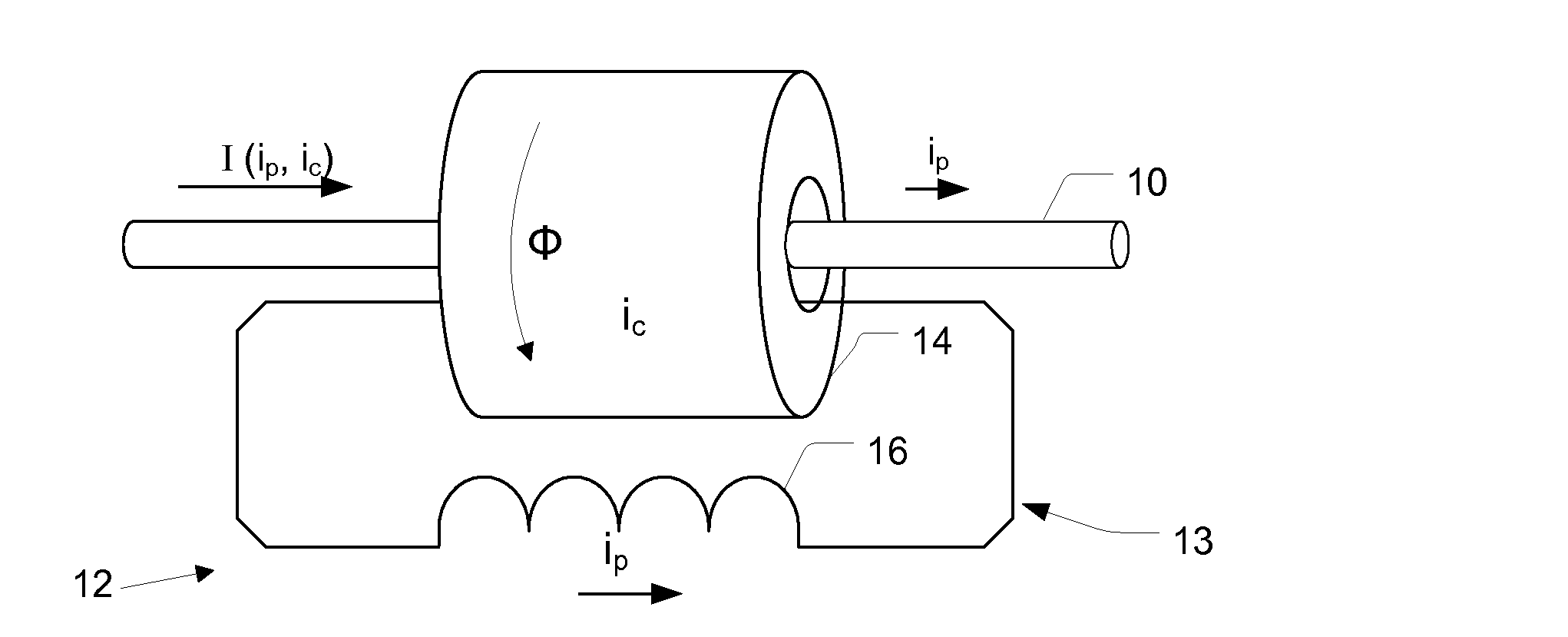
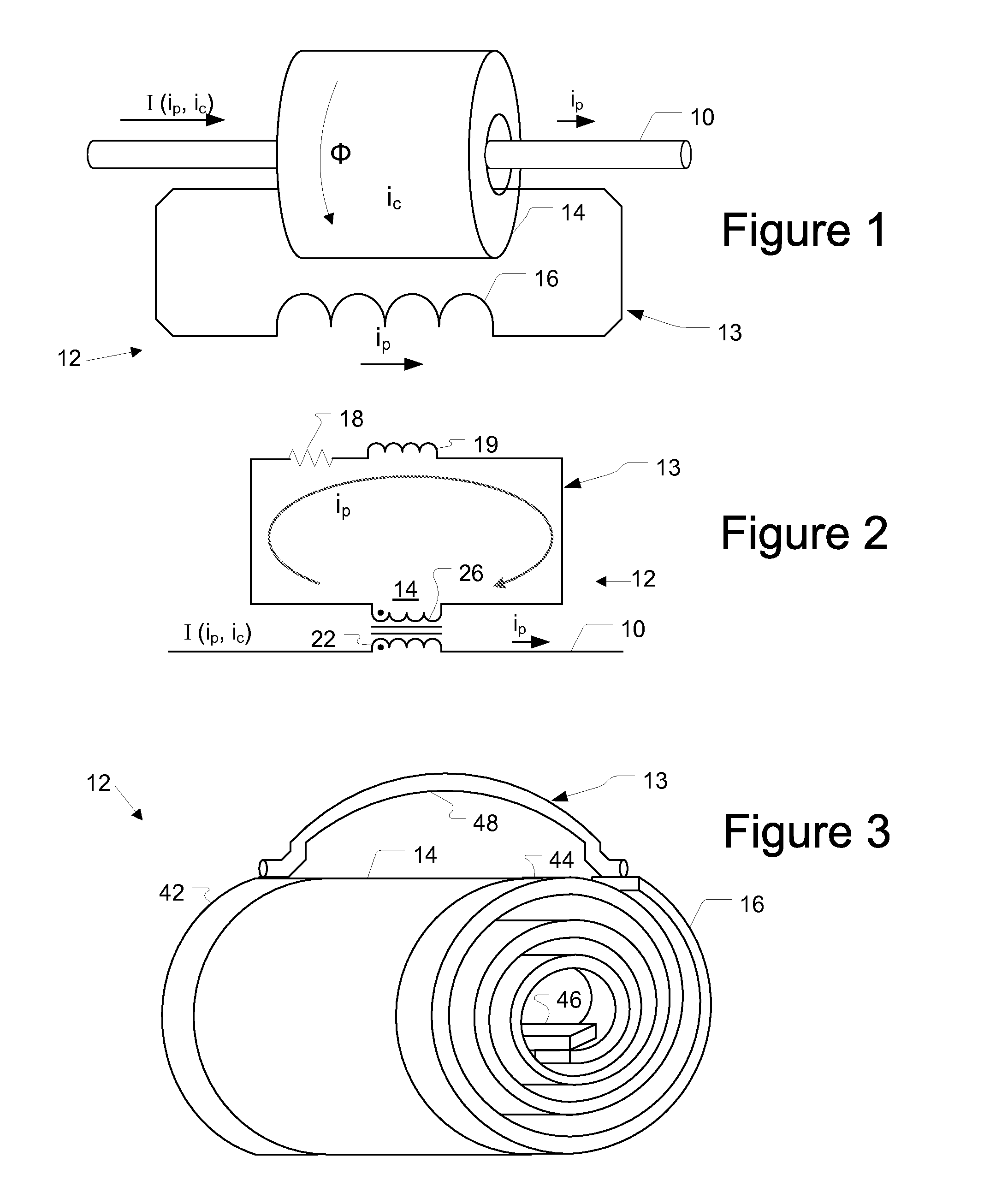
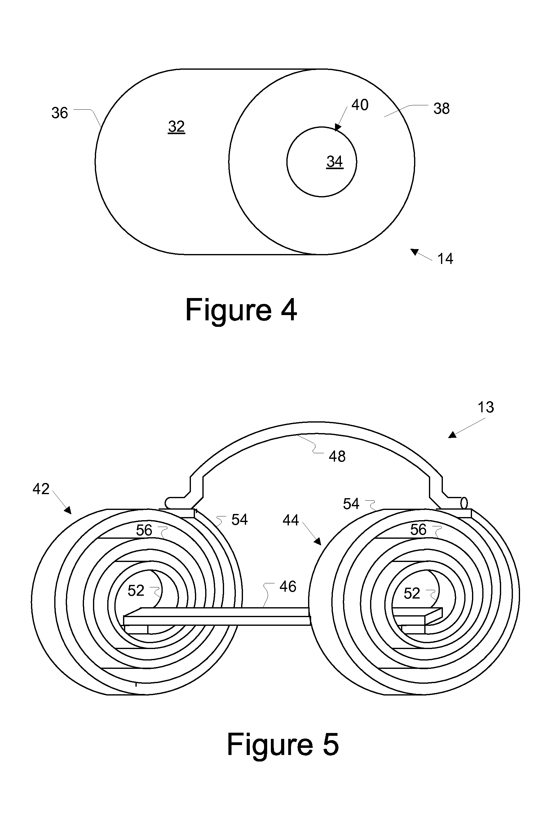
[0008]The present invention provides device and method for attenuating high frequency signals on a power line carrying power. In one embodiment the device may include a toroid shaped core formed of magnetically permeable material and having an inner surface to be disposed substantially around the entire circumference of the power line and a winding formed of a conductor that encircles the toroid. The conductor may include a first spiral coil comprised of a plurality of insulated loops such as concentric loops. The first coil is configured to act as an impedance to high frequency signals traversing the conductor and to allow signals below one hundred hertz to traverse the conductor substantially unimpeded to thereby prevent saturation of the core by the power carried by the power line.

Problems solved by technology

However, the same data signal also may traverse additional unintended paths.
The reception of data signals by devices that are not the desired receiving device may have one or more undesirable consequences.
Thus, the unintended data signal will, in essence, be interference (e.g., noise) to the data signals that are intended for the receiving device.
This may increase latency of communications through the unintended receiving device.
Further, in some instances the transmitting device may undesirably receive the transmitted data signal.
Security is yet another issue.
One adverse effect may be decreased performance of a portion or sub-network of the power line communication system.
In summary, data signals received (whether as noise or data) by unintended devices may degrade network performance.
However, in many systems this architecture is impossible or impractical.
It is impractical to cut power lines to insert filters for attenuating data signals.
However, the power lines carry high voltages and high currents.
The high currents of the power lines often saturate the toroid thereby reducing its effectiveness for attenuating data signals.
However, larger toroids, which are typically constructed of ferrite, become too heavy and / or large for practical deployment.
Providing an air gap in the toroid simply reduces the effectiveness for attenuating data signals by reducing its inductance.

Method used


Image

  • Power Line Data Signal Attenuation Device and Method
  • Power Line Data Signal Attenuation Device and Method
  • Power Line Data Signal Attenuation Device and Method

Examples


Embodiment Construction

[0019]In the following description, for purposes of explanation and not limitation, specific details may be set forth, such as particular networks, communication systems, devices, components, techniques, data and network protocols, software, PLCS, hardware, interfaces, etc. in order to provide a thorough understanding of the present invention. However, it will be apparent to one skilled in the art that the present invention may be practiced in other embodiments that depart from these specific details. Detailed descriptions of well-known networks, communication systems, computers, terminals, devices, PLCS, components, techniques, data and network protocols, software products and systems, operating systems, development interfaces, and hardware are omitted so as not to obscure the description of the present invention.

[0020]As used herein, “filtering” is meant to refer to the attenuation of a signal or to impede a signal. Consequently, “filtering” is not meant to be limited to (or be eq...


PUM


Abstract

A device and method for attenuating high frequency signals on a power line carrying power is provided. In one embodiment the device may include a toroid shaped core formed of magnetically permeable material and having an inner surface to be disposed substantially around the entire circumference of the power line and a winding formed of a conductor that encircles the toroid. The conductor may include a first spiral coil comprised of a plurality of insulated loops such as concentric loops. The first coil is configured to act as an impedance to high frequency signals traversing the conductor and to allow signals below one hundred hertz to traverse the conductor substantially unimpeded to thereby prevent saturation of the core by the power carried by the power line.

Description

FIELD OF THE INVENTION[0001]The present invention generally relates to data communications over a power distribution system, and more particularly to a method and device for attenuating data signals communicated over a power line.BACKGROUND OF THE INVENTION[0002]With some modification, the infrastructure of existing power distribution systems may be used to provide data communication services to customer premises. In a power line communication system (PLCS), existing power lines that already have been run may be used to carry data signals to and from homes, offices, and other structures. These data signals are communicated on and off the power lines at various points in the power line communication system, such as, for example, near homes, offices, Internet service providers, and the like.[0003]Power distribution systems include numerous sections, which conduct power at different voltages. The transition from one section to another typically is accomplished with a transformer. For e...

Claims


Application Information

Patent Timeline
IPC IPC(8): H03H7/01
CPCH02M1/126H03H1/0007H03H2001/0035
Inventor RADTKE, WILLIAM O.
Owner CURRENT TECH
Learn More