
System, method, and apparatus for slit shroud with integrated bypass channel wall feature for disk drive applications

a technology of bypass channel and wall feature, applied in the field of disk drives, can solve the problems of reducing the effectiveness of both bypass channels, and achieve the effects of reducing air leakage, reducing discontinuity in bypass channels, and sufficient surface area

Inactive Publication Date: 2008-04-24
WESTERN DIGITAL TECH INC
View PDF7 Cites 6 Cited by
  • Summary
  • Abstract
  • Description
  • Claims
  • Application Information

AI Technical Summary

Benefits of technology

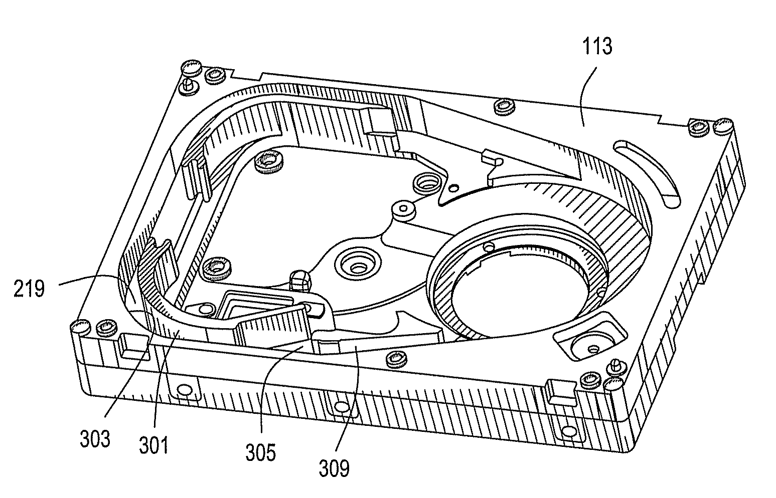
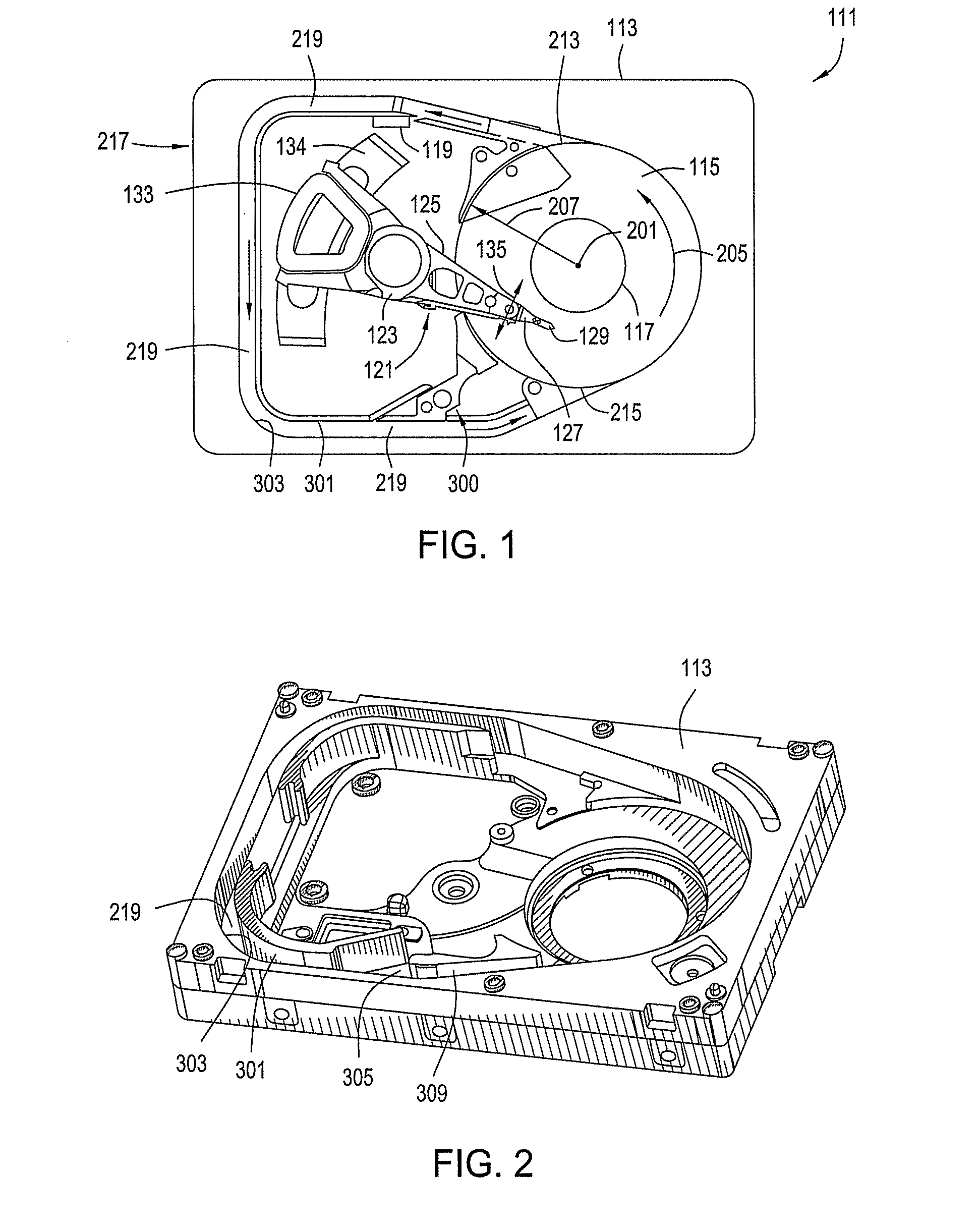
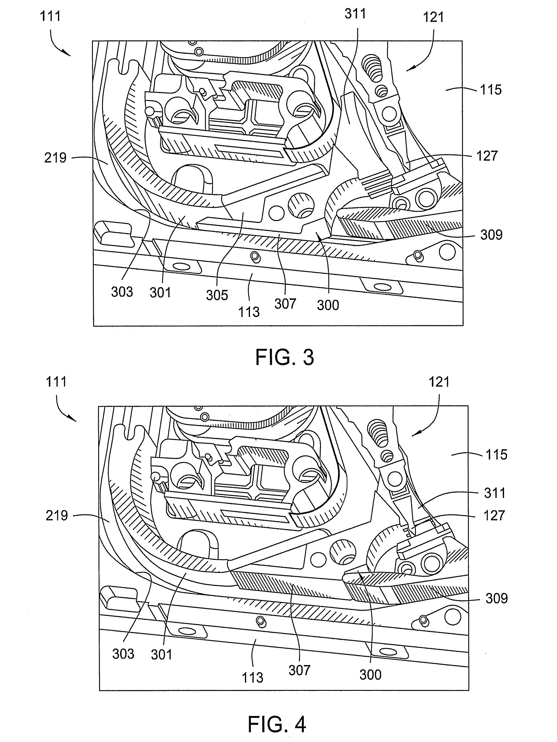
[0012]One embodiment of a system, method, and apparatus for a disk drive slit shroud mitigates a discontinuity in the bypass channel with a wall feature in the slit shroud. When installed, the wall feature fills the gap in the wall of the bypass channel that would otherwise be required to accommodate a slit shroud of sufficient surface area. The bypass channel is most effective when designed into the base casting of the disk drive. In one embodiment, the discontinuity in the channel wall is needed for manufacturing clearance during the installation of the slit shroud. The slit shroud design includes the wall feature which, when installed, fills up the gap in the channel wall to maintain a relatively flush conduit for the bypass channel such that air leakage is minimized.
[0013]The invention is highly effective for some disk drive applications due to the limited disk drive “real estate” or surface area available in the disk drive, and for manufacturing process requirements. The bypass channel wall continuity must be compromised in some disk drive applications so that the slit shroud can be installed. The violation of the bypass wall continuity reduces the effectiveness of both the bypass channel because of reduced pressure and the slit shroud due to the addition of airflow disturbance from bypass channel leakage. The invention overcomes the limitations and makes limited area drives compatible with slit shrouds.

Problems solved by technology

The violation of the bypass wall continuity reduces the effectiveness of both the bypass channel because of reduced pressure and the slit shroud due to the addition of airflow disturbance from bypass channel leakage.

Method used


Image

  • System, method, and apparatus for slit shroud with integrated bypass channel wall feature for disk drive applications
  • System, method, and apparatus for slit shroud with integrated bypass channel wall feature for disk drive applications
  • System, method, and apparatus for slit shroud with integrated bypass channel wall feature for disk drive applications

Examples


Embodiment Construction

[0021]Referring to FIG. 1, one embodiment of a system, method, and apparatus for an information storage system comprising a magnetic hard disk file or drive 111 for a computer system having a lightweight spoiler wing design is shown. Drive 111 has an outer housing including a base 113 and top cover (not shown). The housing contains a disk pack having at least one media disk, e.g., magnetic disk 115. The disks 115 are rotated (see arrows 205) by a spindle motor assembly having a central drive hub 117. An actuator 121 comprises a plurality of parallel actuator arms 125 in the form of a comb that is movably or pivotally mounted to base 113 about a pivot assembly 123. A controller 119 is also mounted to base 113 for selectively moving the comb of arms 125 relative to disk 115.

[0022]In the embodiment shown, each arm 125 has extending from it at least one cantilevered load beam and suspension 127. A magnetic read / write transducer or head is mounted on a slider 129 and secured to a flexure...


PUM


Abstract

A disk drive slit shroud mitigates a discontinuity in the bypass channel with an additional wall feature formed on the slit shroud. When installed, the wall feature fills the gap in the wall of the bypass channel that would otherwise be required to accommodate a slit shroud of sufficient surface area. The discontinuity in the channel wall is needed for manufacturing clearance during the installation of the slit shroud. The slit shroud design includes the wall feature which, when installed, fills up the gap in the channel wall to maintain a relatively flush conduit for the bypass channel.

Description

BACKGROUND OF THE INVENTION[0001]1. Technical Field[0002]The present invention relates in general to disk drives and, in particular, to an improved system, method, and apparatus for a slit shroud with an integrated bypass channel wall feature for disk drive applications.[0003]2. Description of the Related Art[0004]Generally, a data access and storage system consists of one or more storage devices that store data on magnetic or optical storage media. For example, a magnetic storage device is known as a direct access storage device (DASD) or a hard disk drive (HDD) and includes one or more disks and a disk controller to manage local operations concerning the disks. The hard disks themselves are usually made of aluminum alloy or a mixture of glass and ceramic, and are covered with a magnetic coating. Typically, one to six disks are stacked on a common spindle that is turned by a disk drive motor at several thousand revolutions per minute (rpm).[0005]A typical HDD also utilizes an actua...

Claims


Application Information

Patent Timeline
IPC IPC(8): G11B33/14
CPCG11B33/148G11B25/043
Inventor CHAN, ANDRE S.CHIANG, CHISINSULLIVAN, JAMES FRANCISHENDRIKS, FERDINAND
Owner WESTERN DIGITAL TECH INC
Learn More