
Electronically tunable dielectric resonator circuits

a dielectric resonator and electric resonator technology, applied in the direction of resonators, basic electric elements, waveguide devices, etc., can solve the problems of high cost, high cost, and high cost of the machining process itself, and achieve the effect of reducing or reducing the precision required for designing

Inactive Publication Date: 2008-04-01
COBHAM DEFENSE ELECTRONICS SYST CORP
View PDF72 Cites 17 Cited by
  • Summary
  • Abstract
  • Description
  • Claims
  • Application Information

AI Technical Summary

Benefits of technology

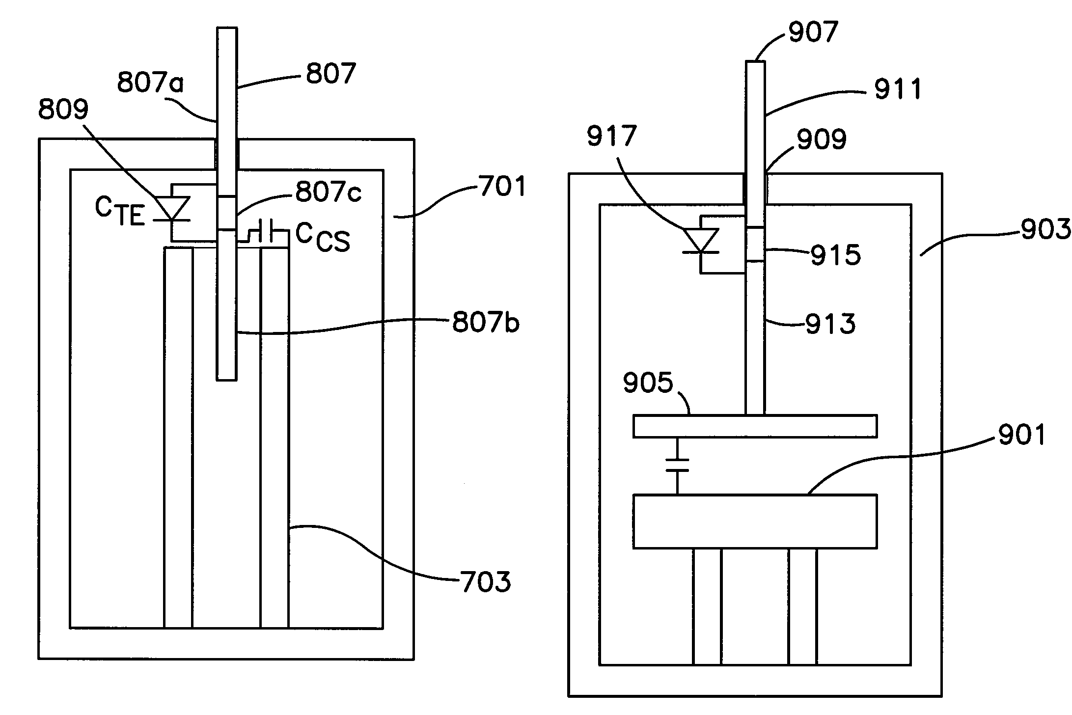
"The present invention provides improved dielectric resonator and combline circuits, as well as improved mechanisms and techniques for tuning the center frequency and frequency of these circuits. The invention allows for electronically tuning the circuits, reducing or eliminating the need for mechanical tuning operations and decreasing the precision required for designing and manufacturing the housing and other physical components of the system. The tuning plates used in the circuit have a conductive portion and an electronically tunable element, which can change the capacitance between the two conductive portions by altering the current or voltage supplied to the electronically tunable element. This allows for precise and efficient tuning of the circuit."

Problems solved by technology

This is a very difficult process that is largely performed by those in the industry empirically by trial and error.
Accordingly, it can be extremely laborious and costly.
Thus, the machining process itself is expensive and error-prone.
Furthermore, the walls within which the irises are formed, the tuning plates, and even the cavity all create losses to the system, decreasing the quality factor, Q, of the system and increasing the insertion loss of the system.
Thus, while the iris walls and tuning plates are necessary for tuning, they are the cause of loss of energy within the system.
This process also can be extremely laborious since each individual dielectric resonator and accompanying tuning plate must be individually adjusted and the resulting response measured.
A disadvantage of the use of tuning screws within the irises is that such a technique does not permit significant changes in coupling strength between the dielectric resonators.
It would be very difficult using tuning screws to adjust the bandwidth of the signal to much greater than 21 or 22 MHz.
There are additional higher order modes, including the TM01 mode, but they are rarely, if ever, used and essentially constitute interference.
Typically, all of the modes other than the TE mode (or H11 mode in filters that utilize that mode) are undesired and constitute interference.
This results in a wide bandwidth operation of the filter.

Method used


Image

  • Electronically tunable dielectric resonator circuits
  • Electronically tunable dielectric resonator circuits
  • Electronically tunable dielectric resonator circuits

Examples


Embodiment Construction

[0037]U.S. patent application Ser. No. 10 / 268,415, which is fully incorporated herein by reference, discloses new dielectric resonators as well as circuits using such resonators. One of the key features of the new resonators disclosed in the aforementioned patent application is that the field strength of the TE mode field outside of and adjacent the resonator varies along the longitudinal dimension of the resonator. As disclosed in the aforementioned patent application, a key feature of these new resonators that helps achieve this goal is that the cross-sectional area of the resonator measured parallel to the field lines of the TE mode varies along the longitude of the resonator, i.e., perpendicular to TE mode field lines. In preferred embodiments, the cross-section varies monotonically as a function of the longitudinal dimension of the resonator. In one particularly preferred embodiment, the resonator is conical. Even more preferably, the cone is a truncated cone. In other preferre...


PUM


Abstract

In order to permit electronic tuning of the frequency of a circuit including dielectric resonators, such as a dielectric resonator filter, tuning plates are employed adjacent the individual dielectric resonators. The tuning plates comprises two separate conductive portions and an electronically tunable element electrically coupled therebetween. The electronically tunable element can be any electronic component that will permit changing the capacitance between the two separate conductive portions of the tuning plates by altering the current or voltage supplied to the electronically tunable element. Such components include virtually any two or three terminal semiconductor device. However, preferable devices include varactor diodes and PIN diodes.

Description

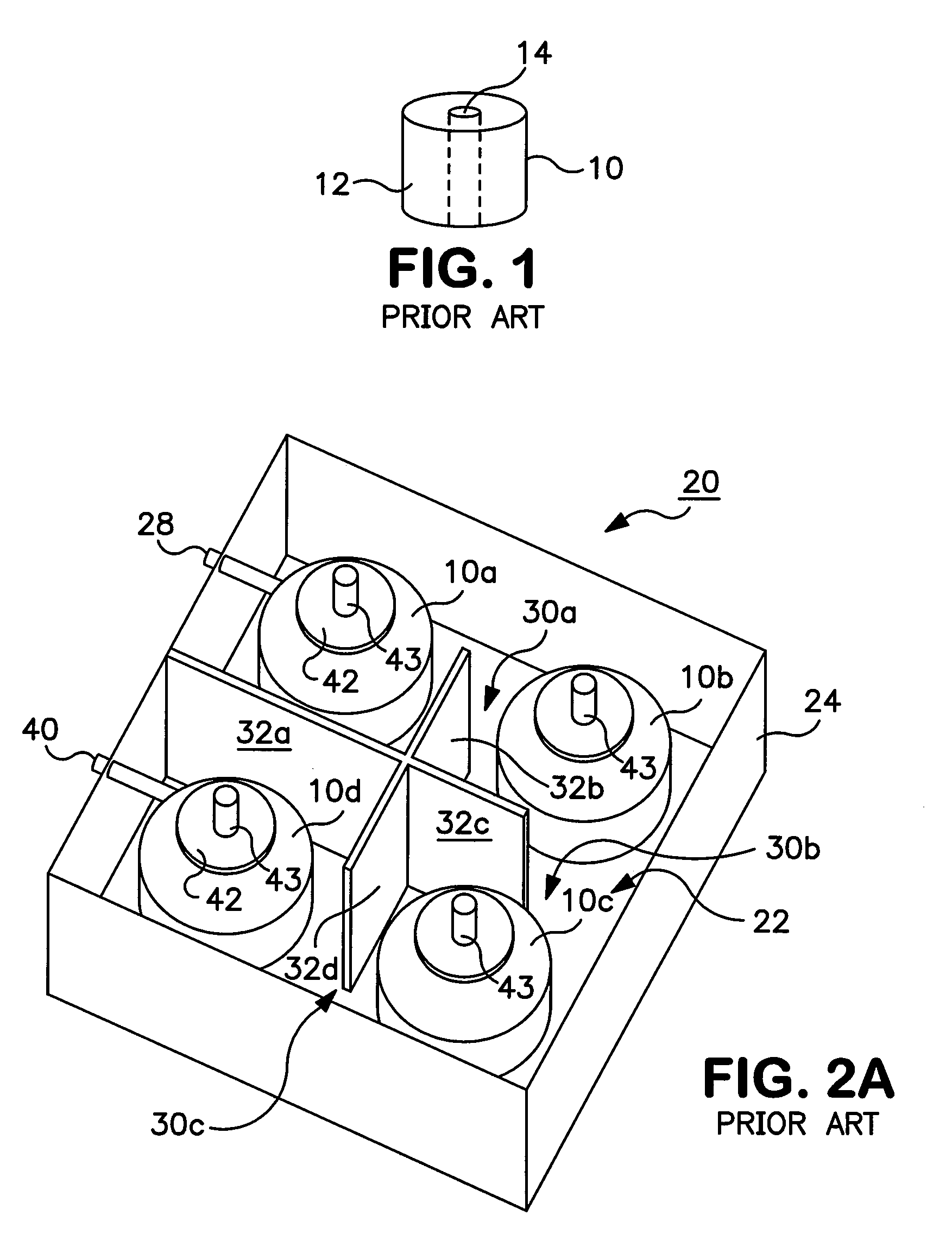
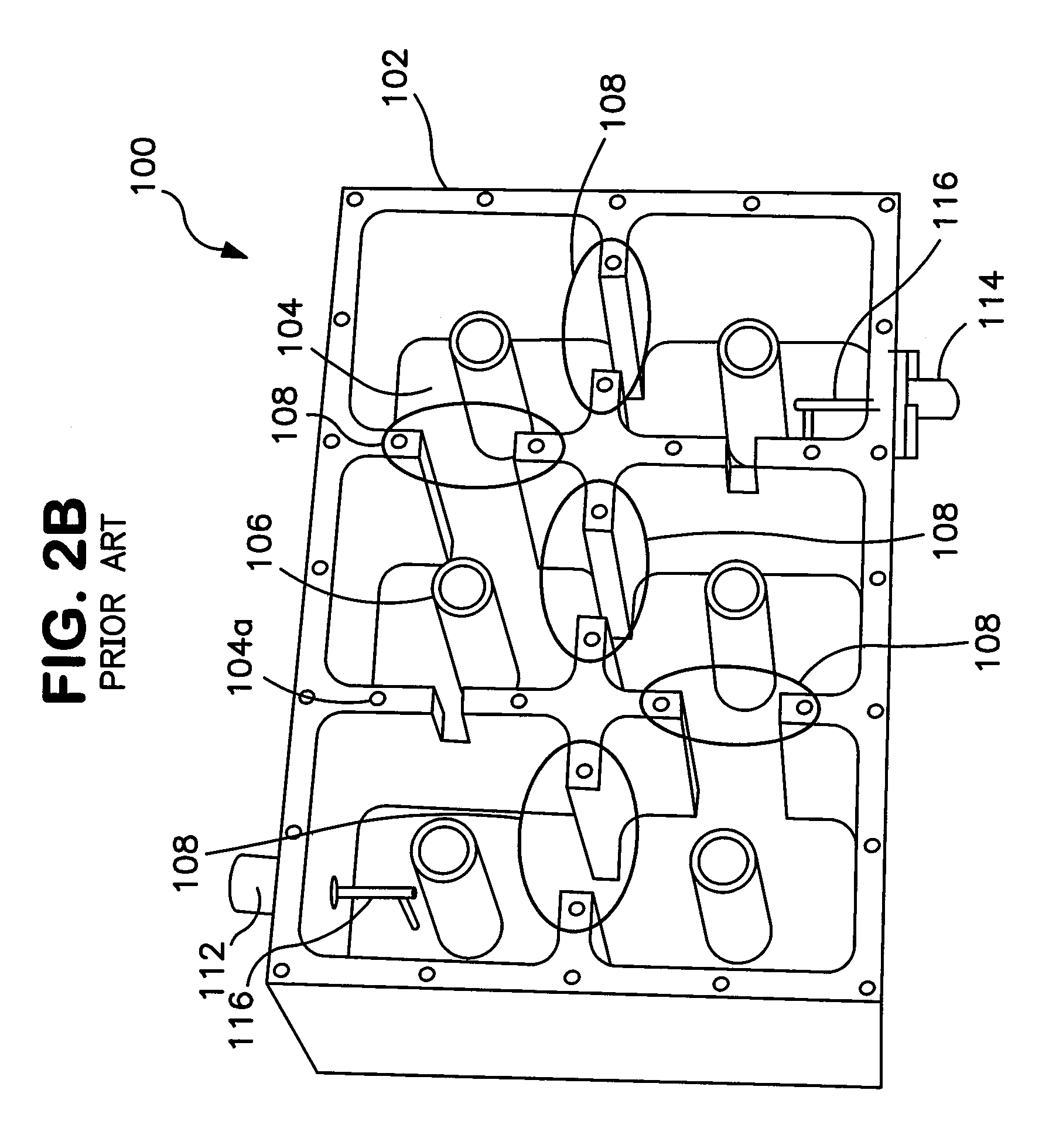
FIELD OF THE INVENTION [0001]The invention pertains to dielectric resonator and combline circuits and, particularly, dielectric resonator and combline filters. More particularly, the invention pertains to techniques for frequency tuning such circuits.BACKGROUND OF THE INVENTION [0002]Dielectric resonators are used in many circuits for concentrating electric fields. They are commonly used as filters in high frequency wireless communication systems, such as satellite and cellular communication applications. They can be used to form oscillators, triplexers and other circuits, in addition to filters. Combline filters are another well known type of circuit used in front-end transmit / receive filters and diplexers of communication systems such as Personal Communication System (PCS), and Global System for Mobile communications (GSM). The combline filters are configured to pass only certain frequency bands of electromagnetic waves as needed by the communication systems.[0003]FIG. 1 is a pers...

Claims


Application Information

Patent Timeline
Patent Type & Authority Patents(United States)
IPC IPC(8): H01P7/10H01P1/20
CPCH01P1/2053H01P1/2084H01P7/10
Inventor SCHWAB, PAUL JOHNPANCE, KRISTI DHIMITERCRAIG, NEIL JAMES
Owner COBHAM DEFENSE ELECTRONICS SYST CORP
Learn More