
Management of microcode lock in a shared computing resource

a technology of shared computing resources and microcode locks, applied in the direction of digital computers, multi-programming arrangements, instruments, etc., can solve the problems of master partition failure, failure to establish a new master, hang or attempt to relinquish its status,

Active Publication Date: 2008-03-25
GOOGLE LLC
View PDF11 Cites 16 Cited by
  • Summary
  • Abstract
  • Description
  • Claims
  • Application Information

AI Technical Summary

Benefits of technology

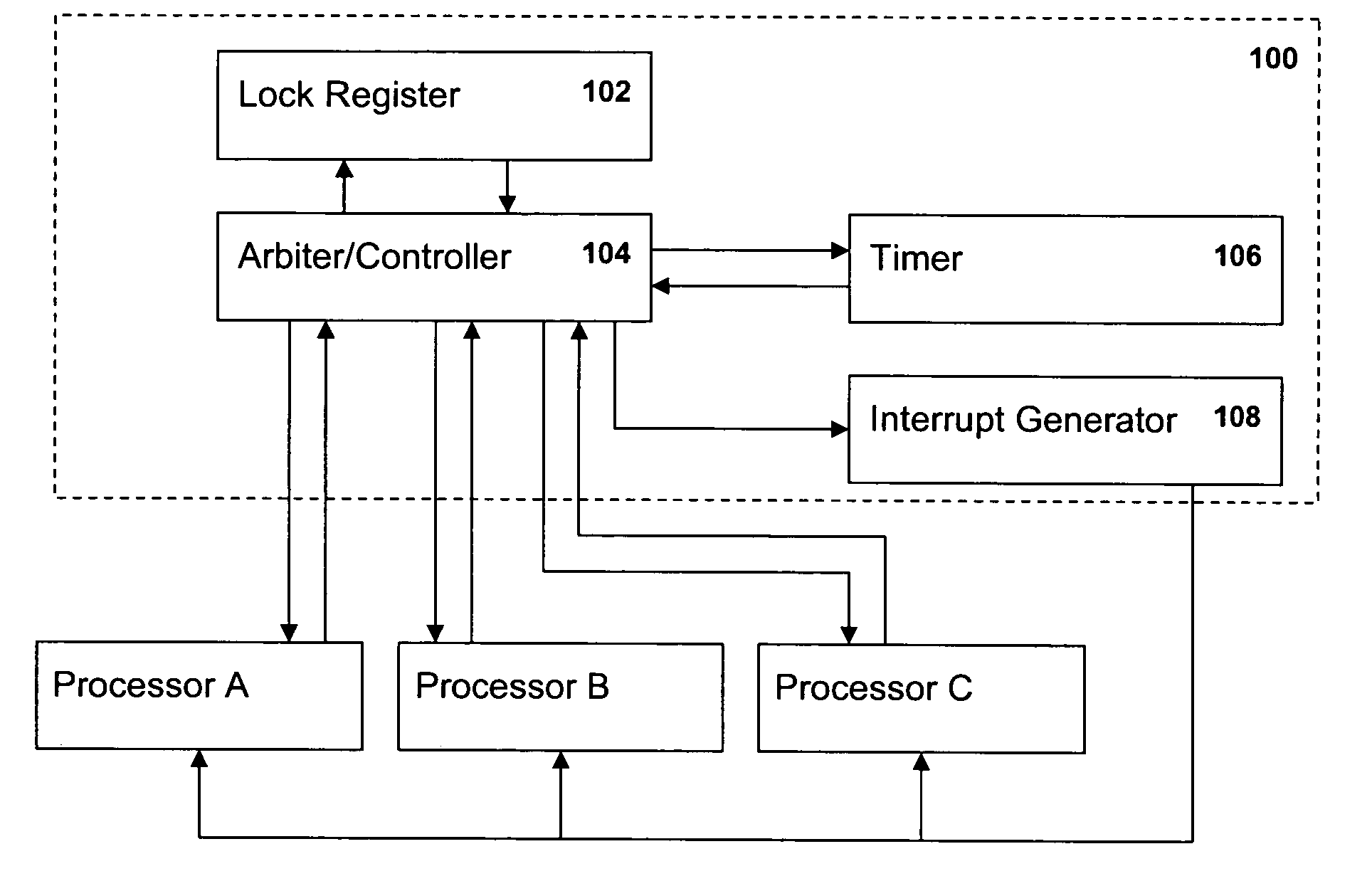
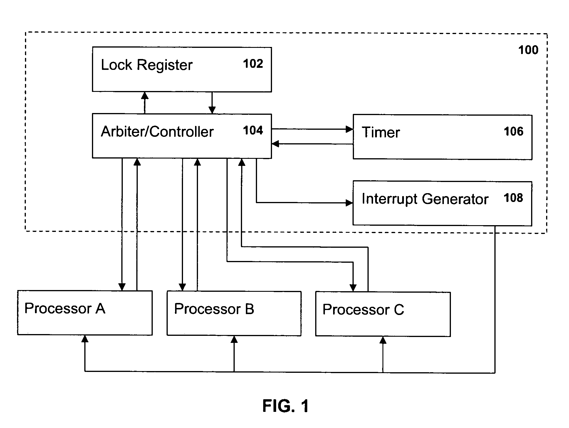
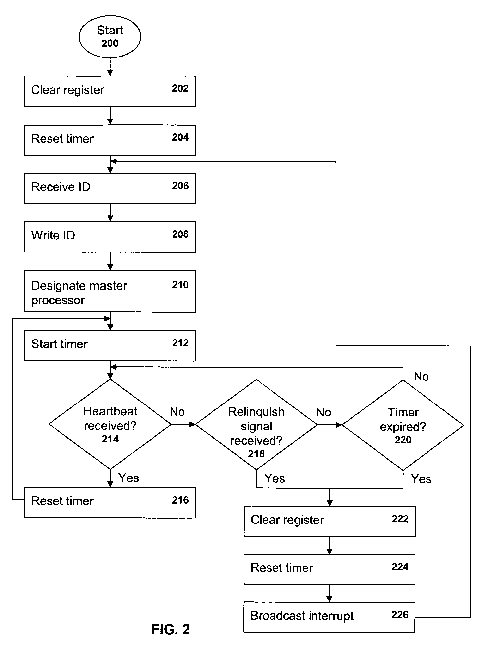
The present invention provides a way to manage a shared computing resource, like a power controller, that is shared by multiple processing units like logical storage controllers. The system includes a lock register and a timing device. The master processor can designate itself as the master processor and control the shared resource. The timer is initialized to count for a predetermined period and the master processor sends a heartbeat signal to the shared resource periodically to keep it running smoothly. If the timer reaches the end of the period without receiving a heartbeat signal, indicating that the master processor has failed, hung or is relinquishing control, the lock register is cleared again and an interrupt signal is broadcast to all the processors. The processors compete for master status anew and, when an ID is successfully written to the lock register, the timer is restarted and the new master periodically transmits its heartbeat signal. An arbiter / controller may be employed as an interface between the processors and the lock register and to start, stop and reset the timer. An interrupt generator may be employed to send the interrupt signal to the processors when triggered if the timer reaches the end of the predetermined period.

Problems solved by technology

Occasionally, a master partition will fail, hang or attempt to relinquish its status as master.
There is currently no procedure to establish a new master in such circumstances.

Method used


Image

  • Management of microcode lock in a shared computing resource
  • Management of microcode lock in a shared computing resource
  • Management of microcode lock in a shared computing resource

Examples


Embodiment Construction

[0008]Although the present invention will be described herein in the context of a power controller and attached partitions, the invention is applicable to other systems and components. Consequently, the power controller may be referred to herein generally as a “shared computing resource” (or simply “resource”) and the partitions may be referred to herein generally as “processors”.

[0009]FIG. 1 is a block diagram of a portion of a shared computing resource in which the lock manager 100 of the present invention may be implemented. Attached to the resource 100, are multiple processors, three of which are shown in FIG. 1 and designated as A, B and C (the three processors A, B and C are representative of any number of processors; it will be appreciated that fewer than or more than three may be attached). The resource 100 includes a microcode lock register 102 in which is stored the address or other ID of the processor designated as the master processor. The resource 100 also includes an a...


PUM


Abstract

In a power controller or other computing resource shared by multiple processors, an ID is written to the lock register, thereby designating a master processor. A timer is then initialized to count for a predetermined period. Periodically, the master processor transmits a “heartbeatsignal to the shared resource, indicating that its operation remains normal. Upon receipt of the heartbeat signal, the timer is reset and begins a new count for the predetermined period. If the timer reaches the end of the period without having received a heartbeat signal, indicating that the master processor has failed or hung, the lock register is cleared again and an interrupt signal is broadcast to all of the processors. The processors compete for master status anew and, when an ID is successfully written to the lock register, the timer is restarted and the new master periodically transmits its heartbeat signal.

Description

TECHNICAL FIELD[0001]The present invention relates generally to computing systems with shared resources and, in particular, to the management of a microcode lock within a shared resource.BACKGROUND ART[0002]In a large scale computing environment, such as one in which one or more storage subsystems are attached to one or more host devices, some computing resources are shared by various components. For example, a storage subsystem may include one or more storage controllers, each having two clusters, each cluster having up to 16 logical storage partitions. A single power controller may be shared among many (or all) of the partitions. The power controller provides power system management for the attached clusters as well as other functions which are common to the clusters and partitions.[0003]Typically, the power controller requires that one of the attached partitions provide processing operations. The conventional process by which a partition is selected is as generally follows. The p...

Claims


Application Information

Patent Timeline
Patent Type & Authority Patents(United States)
IPC IPC(8): G06F11/00
CPCG06F9/526G06F11/0757
Inventor GARCIA, ENRIQUE
Owner GOOGLE LLC
Learn More