
GPS receiver using stored navigation data bits for a fast determination of GPS clock time

a technology of gps receiver and stored navigation data, which is applied in the field of gps receiver, can solve the problems of not being able to determine its position, adding hardware cost or power consumption, or both, and achieves the effect of fast time to first fix and/or low power consumption, and excessive hardware cos

Active Publication Date: 2008-03-25
TRIMBLE NAVIGATION LTD
View PDF14 Cites 30 Cited by
  • Summary
  • Abstract
  • Description
  • Claims
  • Application Information

AI Technical Summary

Benefits of technology

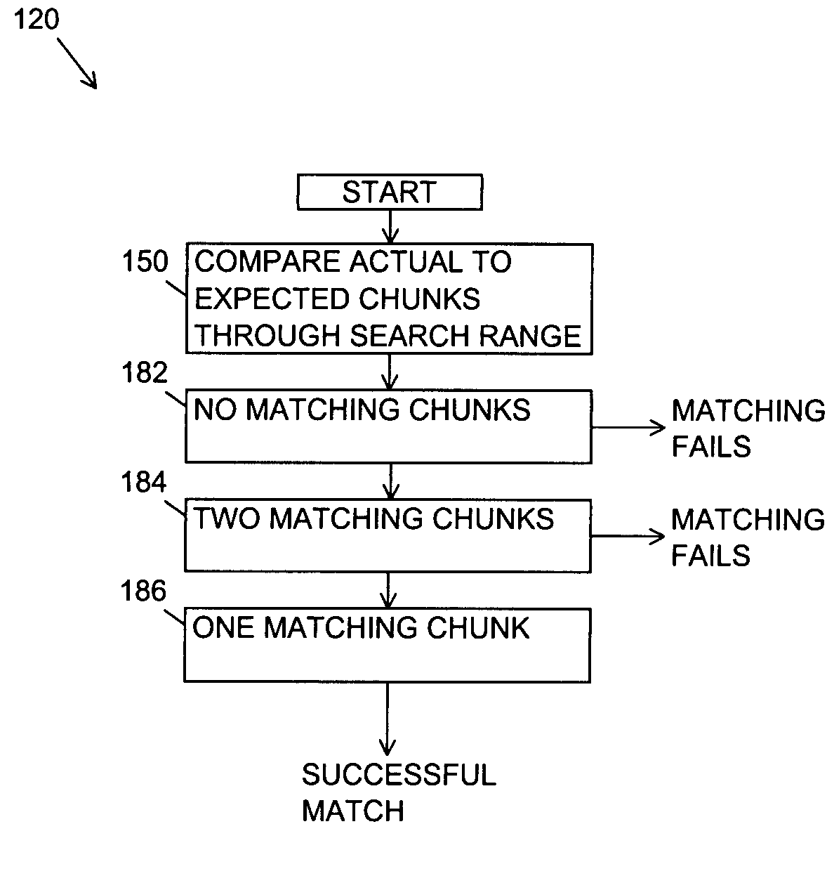
The present invention provides a GPS receiver and method that can quickly fix a position without needing to wait for a certain number of GPS signals to arrive. This is done by storing expected GPS data bits and comparing them to the current GPS signals. The invention also minimizes power consumption by only turning on the GPS receiver when needed. The GPS receiver can be in a standby mode and quickly enter an operation mode when needed. The invention uses a coarse time estimate to identify a search range or time-of-entry, and then compares chunks of the expected GPS data bits to the current data bits to refine the estimate. The invention can be used in both an anytime embodiment and a focused embodiment.

Problems solved by technology

At this point the GPS receiver knows the timing of the GPS data bits but it cannot determine its position because it does not yet know the absolute GPS clock time.
A limitation of the above-described conventional hot start is that the GPS receiver must monitor the GPS messages data bits for up to six seconds or about three seconds on the average to receive one-half subframe for a TLM word; or about nine seconds on the average to receive one and one-half subframes in order to verify that a first TLM word is not a random event of bits.
However, these methods for providing ten millisecond or better time accuracy add hardware cost or power consumption or both in the GPS receiver.

Method used


Image

  • GPS receiver using stored navigation data bits for a fast determination of GPS clock time
  • GPS receiver using stored navigation data bits for a fast determination of GPS clock time
  • GPS receiver using stored navigation data bits for a fast determination of GPS clock time

Examples


Embodiment Construction

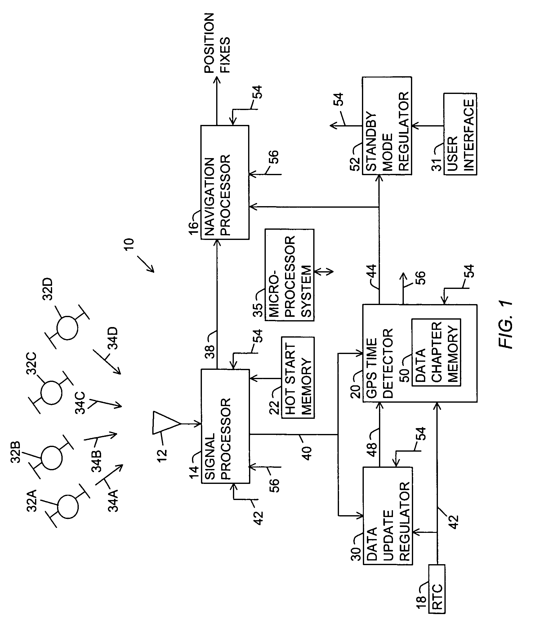
[0026]FIG. 1 is a block diagram of a global positioning system (GPS) receiver of the present invention referred to with a reference number 10. The GPS receiver 10 includes a GPS antenna 12, a signal processor 14, a navigation processor 16, a real time clock (RTC) 18, a GPS time detector 20, a hot start memory 22, a data update regulator 30 and a user interface 31. GPS signal sources 32A-D broadcast respective GPS signals 34A-D. The GPS signal sources 32A-D are normally GPS satellites. However, pseudolites may also be used. For convenience the GPS signal sources 32A-D are referred to as GPS satellites 32 and the GPS signals 34A-D are referred to as GPS signals 34 with the understanding that each of the GPS signals 34A-D is broadcast separately with separate GPS message data for each of the GPS signal sources 32A-D. A global navigation satellite system (GNSS) signal source and signal may be used in place of the GPS signal sources 32 and GPS signals 34.

[0027]In order to more easily und...


PUM


Abstract

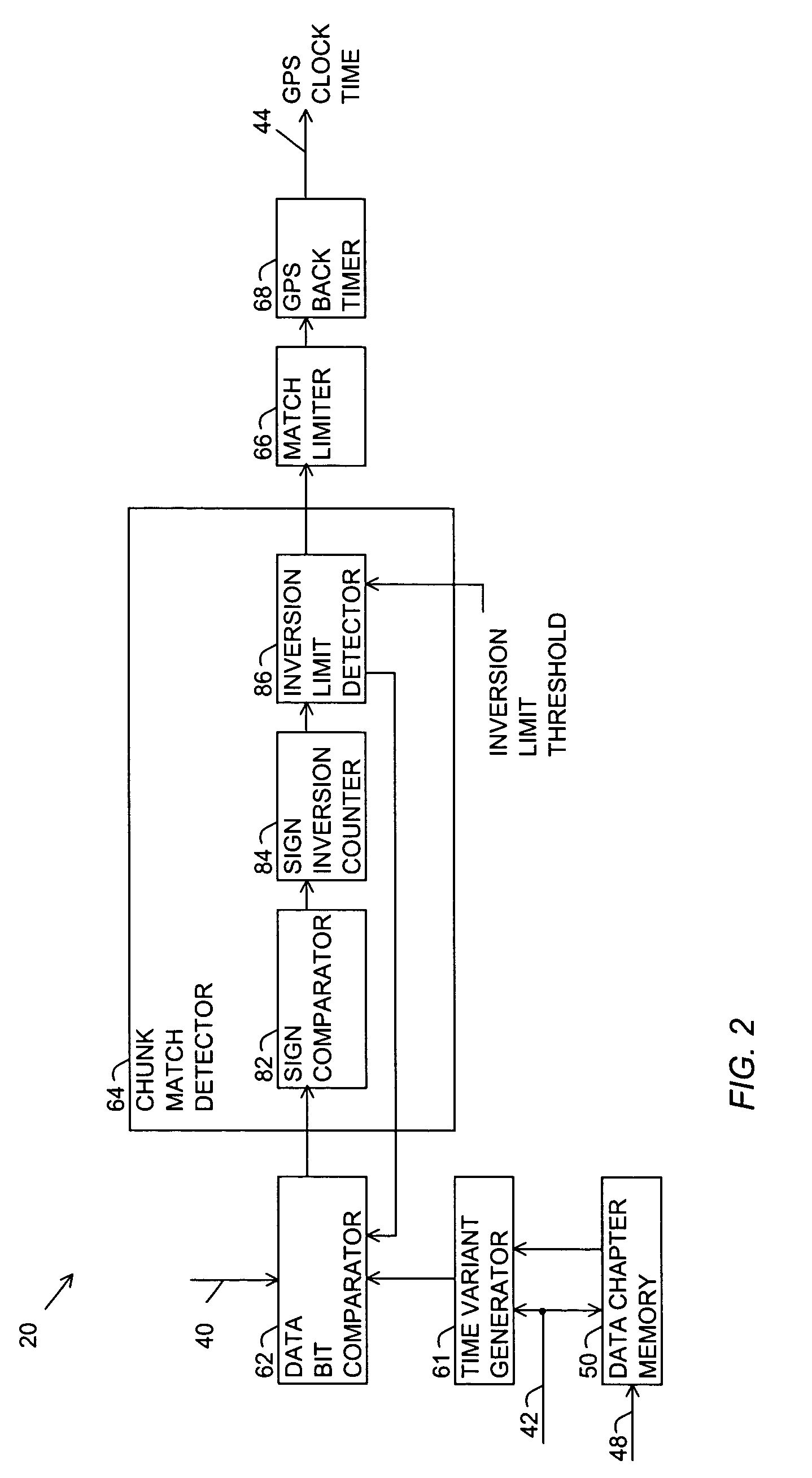
A GPS receiver having a fast method for determining GPS clock time. The GPS receiver includes a signal processor for receiving GPS signals from GPS satellites and detecting current GPS data bits carried by the respective GPS signals, a chapter memory for storing a block of expected GPS data bits for the respective GPS satellites, and a GPS time detector for detecting a successful match when a chunk of the expected data bits within a selected search range within the block matches a chunk of the current data bits, and using the successful match for determining the GPS clock time. In an anytime embodiment the GPS receiver enters an operation mode at any time in order to minimize user request latency. In a focused embodiment the GPS receiver enters the operation mode at a prescribed time-of-entry in order to minimize power consumption for cycles of standby and operation modes.

Description

BACKGROUND OF THE INVENTION[0001]1. Field of the Invention[0002]The invention relates generally to global positioning system (GPS) receivers and more particularly to a GPS receiver having fast time to first fix by comparing a chunk of received data bits to chunks of expected data bits within a designated search range of an expected GPS data message.[0003]2. Description of the Prior Art[0004]The global positioning system (GPS) is a system using GPS satellites for broadcasting GPS signals having information for determining location and time. Each GPS satellite broadcasts a GPS signal having message data that is unique to that satellite. The message for a Coarse / Acquisition (C / A) format of the GPS signal has data bits having twenty millisecond time periods. The twenty millisecond data bits are modulated by a one millisecond pseudorandom noise (PRN) code having 1023 bits or chips. The PRN code for each GPS satellite is distinct, thereby enabling a GPS receiver to distinguish the GPS sig...

Claims


Application Information

Patent Timeline
Patent Type & Authority Patents(United States)
IPC IPC(8): G01S5/14G01S19/24
CPCG01S19/24
Inventor YU, YIMING
Owner TRIMBLE NAVIGATION LTD
Learn More